background image

ated with this Spindle Moulder. Accidents are

No list of safety guidelines can be complete. 

Every shop environment is different. Always 

consider  safety  first,  as  it  applies  to  your 

individual working conditions. Use this and 

other  machinery  with  caution  and  respect. 

Failure to do so could result in serious per-

sonal injury, damage to equipment, or poor 

work results.

Like  all  machines  there  is  danger  associ-

frequently  caused  by  lack  of  familiarity  or 

failure  to  pay  attention.  Use  this  machine 

with respect and caution to lessen the pos-

sibility  of  operator  injury.  If  normal  safety 

precautions are overlooked or ignored, seri-

ous personal injury may occur.

Additional Safety Instructions for Shapers

1.


HAND  POSITIONING.

  Never  place  hands 

directly over or in front of the cutter. As one 
hand  approaches  the  cutter,  move  it  in  an 
arc  motion  away  from  the  cutter  to  the  out-
feed side. Always keep hand at least 6" away 
from the cutter while operating.

2.  SAFETY  DEVICES.

  Use  a  fixture,  jig,  or 

hold-down  device  to  decrease  the  chances 
of injury.

3.  SAFETY  GUARDS.

  DO  NOT  remove  the 

retractable guard on the fence. Use a guard 
or other type of protective device at all times. 
Use  overhead  guard  when  the  fence  is 
removed.

4.  CUTTER HEIGHT. 

Keep any unused portion 

of the cutter below the table surface.

5.


STOCK LENGTH.

 Do not use stock shorter 

than 6 inches without special fixtures or jigs. 
Where practical, shape longer stock and cut 
to size.

6.


STOCK  CONDITION. 

The  danger  of  kick-

back is increased when the stock has knots, 
holes, or foreign objects in it. Warped stock 
should  be  run  through  a  jointer  before  you 
run it through a shaper.

7.


BLIND  CUT  WHEN  POSSIBLE.

  Blind  cuts 

keep  the  cutters  on  the  underside  of  the 
workpiece and provide a distance guard for 
the operator. 

8.  TEST  ROTATION.

  With  the  machine 

unplugged,  rotate  the  spindle  to  test  any 
new setup to ensure proper cutter clearance 
before starting the machine.

9.  DEPTH  OF  CUT.

  Never  remove  too  much 

material  in  one  pass.  Several  light  passes 
are safer and produce a cleaner finish.

10.  SHAPING  CONTOURED  WORK.

  Always 

use  a  rub  collar  and  a  template.  DO  NOT 
start out at a corner. See the rub collar sec-
tion further on in the manual.


11.


FEEDING  THE  WORKPIECE.

  Always  feed 

the workpiece against the rotation of the cut-
ter. Never force materials through the shaper. 
Let the cutters do the work. Excessive force 
is likely to result in poor cutting results and 
will cause dangerous kickback conditions. 

12.


SECURING  NUTS  AND  KNOBS. 

Never 

operate the shaper without the second lock-
ing nut in place over the spindle nut. Always 
ensure  that  the  cutters,  fence,  and  spindle 
elevator knob have been tightened properly 
before beginning any operation.

5

Summary of Contents for G1026

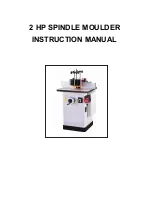
Page 1: ...2 HP SPINDLE MOULDER INSTRUCTION MANUAL ...

Page 2: ... 1 ...

Page 3: ...Contents SECTION 1 SAFETY 3 Additional Safety Instructions for Shapers Controls Features Unpacking Piece Inventory Hardware Recognition Chart Site Considerations Beginning Assembly Handwheel Spindle Table Inserts Extension Wing Fence Assembly Rotation Speed Changes General Lubrication Table V Belt Spindle Bearings Pulley Alignment V Belt Tension Truing The Fence Gib Adjustments Machine Data Sheet ...

Page 4: ... SECTION 1 SAFETY 3 ...

Page 5: ... 4 ...

Page 6: ...sed portion of the cutter below the table surface 5 STOCK LENGTH Do not use stock shorter than 6 inches without special fixtures or jigs Where practical shape longer stock and cut to size 6 STOCK CONDITION The danger of kick back is increased when the stock has knots holes or foreign objects in it Warped stock should be run through a jointer before you run it through a shaper 7 BLIND CUT WHEN POSS...

Page 7: ... recommend that you become familiar with the basic features of your new shaper Please match up the list below with the letters in Figure to identify the shaper controls and features A Guide B Vertical Bar C Adjustment Level D E Table F G H Scale I Reverse Switch Figure 6 J K Motor Cover Handwheel On Off Switch Stand B A C D E F G H I J K ...

Page 8: ...sem bly or to identify missing parts please refer to the detailed illustrations at the end of the manual After all the parts have been removed from the carton you should have 7 over exert yourself while unpacking or moving your machine consider using power equipment to move the machine Serious per sonal injury may occur if safe moving methods are not followed heavy machine 4mm Hex Wrench 1 5mm Hex...

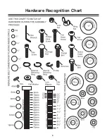
Page 9: ...Hardware Recognition Chart 8 ...

Page 10: ...mbined motor amp loads Outlets should be located near each machine so power or exten sion cords are not obstructing high traffic areas Be sure to observe local electrical codes for prop er installation of new lighting outlets or circuits The unpainted surfaces are coated with a waxy oil to protect them from corrosion during ship ment Remove this protective coating with a sol some parts may need to...

Page 11: ...ailure to do so could result in injury Disconnect power from the machine when per forming any maintenance assembly or adjustments Failure to do this may result in serious personal injury 10 To install the handwheel 1 Insert the handwheel on the handwheel shaft shown in Figure Figure Location of handwheel shaft Handwheel Handwheel 2 Tighten the handwheel knob against the screw part of the handwheel...

Page 12: ...M POWER 2 Remove the hex nuts from the spindle and the drawbar nut from the drawbar 3 Thread the drawbar approximately 10 15 turns into the bottom of the spindle The drawbar has two threaded ends One of them remains exposed See Figure Figure Spindle and drawbar 10 15 Turns Spindle Drawbar 11 spindles Figure Inserting the spindle into place 4 Place the spindle drawbar into the spindle cartridge at ...

Page 13: ...the top of the table To adjust the insert 1 KEEP SHAPER DISCONNECTED FROM POWER 2 Remove the three Phillips head screws that hold the cast iron insert in place 12 7 7 4 Replace and tighten the Phillips head screws and inspect with a straightedge Figure Leveling table insert 3 Using a straightedge and a flathead screw driver turn the barrel screws clockwise or counterclockwise to level the cast iro...

Page 14: ...ts and that the bolts are tight Note The end of the wing at the last bolt may not be flush with the surface of the table Don t be alarmed 13 Inspect your results with a good quality straightedge Fence Assembly To install the fence assembly 1 KEEP SHAPER DISCONNECTED FROM POWER 2 shown in Figure 1 Figure 1 Fence assembly 3 Secure the fence pieces with lock knob 4 Insert the hexason bar to socket ti...

Page 15: ... position 6 Listen to and watch for abnormal noises or actions The machine should run smoothly with little or no vibration or rubbing noises Immediately turn the shaper OFF if you suspect any problems and fix any prob lems before starting the shaper again Wear safety glasses dur ing the entire operation process Failure to com ply may result in serious personal injury Disconnect power to the machin...

Page 16: ...signed to withstand the vibration and sudden shock loads associated with the operation of a shaper To change spindle speeds 1 DISCONNECT SHAPER FROM POWER SOURCE 2 Loosen the two motor mount bolts and slide the motor toward the spindle assembly by tu DO NOT take the bolts out 3 Move the V belt to a sheave on the motor and spindle pulleys to select the desired speed See Figure 14 Figure 14 Speed ch...

Page 17: ...equire peri odic lubrication are the ways where the cartridge slide rides on the elevation housing and where the worm gear and bushing are located Use a light grease or anti seizing compound on the ways and worm gear and give the shaft mount a shot of light oil The frequency of lubrication depends on the amount you use the shaper As a habit inspect the machine at least once a month Wear safety gla...

Page 18: ... the housing back in reverse the procedure Make sure the locking bolt is tightened securely SECTION 6 SERVICE ADJUSTMENTS Keep clothing rolled up and out of the way of machinery and keep hair pulled back Wear safety glasses dur ing the entire adjustment process Failure to com ply may result in serious personal injury Disconnect power to the machine when perform ing any maintenance or assembly Fail...

Page 19: ...lt is small and runs fast this much tension is necessary The V Belt will slip if too loose and squeal or cause vibration if too tight Adjust the tension if necessary To adjust V Belt tension 1 DISCONNECT SHAPER FROM POWER SOURCE 2 Make sure the pulleys are properly aligned 3 Loosen the two motor mount plate bolts and slide the motor left or right to modify the belt tension Keep the pulleys aligned...

Page 20: ...ack between the elevation housing and spindle cartridge slide by tightening the four 5 16 setscrews with a 4mm hex wrench Alternate between the upper and lower adjustments to ensure consistent tightness Failure to do so may cause disappointing results DO NOT over tighten the gib Over tightening will restrict spindle movement Loosen the spindle assembly lock knob and raise or lower the spindle to c...

Page 21: ...el L610 W534mm 150Kgs 130Kgs L670 W575 H1100mm 75mm 7 000 10 000 R P M 60HZ Cast Iron Cast Iron Cast Iron Sheet Metal 2 HP 2 850 R P M 50 HZ On Off Switch Reverse Switch Powerful 2HP motors delivers smooth consistent power on even heavy duty jobs Staring pin for irregular shaping Two speed step pulley drive lets you select the best speed and toeque for different cutter diameters Independent left a...

Page 22: ...21 ...

Page 23: ...22 ...

Page 24: ...23 ...

Page 25: ...24 ...

Page 26: ...25 ...

Page 27: ...26 ...

Page 28: ...27 ...

Page 29: ...28 ...

Reviews: