background image

Model g0493 (Mfg. since 7/10)

-59-


note: 

We recommend cutting the hardwood 

board  oversize,  then  jointing  and  planing  it 
to  the  correct  size  to  make  sure  the  board 
is  square  and  flat.  Only  use  furniture  grade 
plywood  or  kiln  dried  hardwood  to  prevent 
warping.

3"

3

4

" Hardwood

5

1

4

"

3

4

" Plywood

Length of Table
Saw Fence

Length of Table
Saw Fence

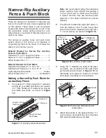
figure 117. auxiliary fence dimensions.

making a narrow-rip push block for 

an auxiliary fence

1.  Cut a piece of 

3

4

" thick plywood 5 

1

4

" wide and 

as long as your table saw fence; cut a piece 
of 

3

4

" thick hardwood 3" wide and as long as 

your  table  saw  fence,  as  shown  in 

figure 

117.

narrow-rip auxiliary 

fence & push block

there  are  designs  for  hundreds  of  specialty  jigs 
that can be found in books, trade magazines, and 
on  the  internet.  these  types  of  jigs  can  greatly 
improve the safety and consistency of cuts. they 
are  particularly  useful  during  production  runs 
when dozens or hundreds of the same type of cut 
need to be made.

the  narrow-rip  auxiliary  fence  and  push  block 
system  shown  in  this  section  is  an  example  of 
a  specialty  jig  that  can  be  made  to  increase  the 
safety of very narrow rip cuts.

2.  pre-drill and countersink eight pilot holes 

3

8

from  the  bottom  of  the  3"  wide  board,  then 
secure  the  boards  together  with  eight  #8  x 
1

1

2

" wood screws, as shown in 

figure 118.

3

4

"

 Plywood

Completed
Fence

3

4

"

 Hardwood

#8 x 1

1

2

"

Wood Screw

figure 118. location of pilot holes.

5


5

8

"

15"

5


1

4

"

12


1

2

"

2


1

2

"


3

8

"

Lip

Handle


3

8

"

5

8

"

2


1

2

"

figure 119. push block dimensions and 

construction.

3.  using the 

3

4

" material you used in the previ-

ous steps, cut out pieces for the push block 
per the dimensions shown in 

figure 119; for 

the handle, cut a piece 10" long by 5"–9" high 
and shape it as desired to fit your hand.

4.  attach the handle to the base with #8 x 1

1

2

wood screws, and attach the lip to the base 
with cyanoacrylate type wood glue.

material  needed  for  narrow  rip  auxiliary 

fence & push block
hardwood 

3

4

" x 3" x length of Fence ................1

plywood 

3

4

" x 5

1

4

" x length of Fence ................1

Wood screws #8 x 1

1

2

" ......................................8

material needed for push block
hardwood or plywood 

3

4

" x 15" x 5

5

8

" ...............1

hardwood or plywood 

3

4

" x 10" x 5"–9"  ............1 

Cyanoacrylate Wood glue .........................varies
Wood screws #8 x 1

1

2

" ......................as needed

Summary of Contents for G0493

Page 1: ...September 2010 TR Warning No portion of this manual may be reproduced in any shape Or form without the written approval of Grizzly Industrial inc For models manufactured Since 7 10 TR9023 printed in...

Page 2: ...personal protective equipment The manufacturer will not be held liable for injury or property damage from negligence improper training machine modifications or misuse Some dust created by power sandin...

Page 3: ...Crosscutting 47 Miter Cutting 49 Dado Cutting 50 Rabbet Cutting 51 Resawing 52 SECTION 5 SHOP MADE SAFETY ACCESSORIES 54 Featherboards 54 Push Sticks 57 Push Blocks 58 Narrow Rip Auxiliary Fence Push...

Page 4: ...k on this manual If you can take the time please email or write to us at the address below and tell us how we did Grizzly Industrial Inc C O Technical Documentation Manager P O Box 2069 Bellingham WA...

Page 5: ...e guard maintains maximum protection around the saw blade and a 2 dust port effectively extracts dust from the cutting operation F Rip Fence Fully adjustable with micro adjustment knob for precision a...

Page 6: ...d preventing tear out in laminate mate rials The scoring blade is adjustable forward and backward up and down and in kerf thickness J Fence Assembly Lock Down Lever Secures the fence assembly into pos...

Page 7: ...e motor cabinet W Scoring Blade ON Button Starts the scor ing blade Note The main saw blade must be ON for the scoring blade to start X Main Blade ON Button Starts the main saw blade Y Scoring Blade E...

Page 8: ...n 1 Type Wood Slat Crate Content Machine Weight 1618 lbs Length Width Height 87 x 56 x 40 in Carton 2 Type Wood Slat Crate Content Sliding Table Weight 323 lbs Length Width Height 132 x 20 x 18 in Ele...

Page 9: ...deg Scoring Blade Speed 8000 RPM Cutting Capacities Max Depth Of Cut At 90D 4 1 8 in Max Depth Of Cut At 45D 2 7 8 in Table With Rip Fence Max Cut Width 48 1 2 in Sliding Table With Cross Fence Max C...

Page 10: ...ce Assembly Construction Extruded Aluminum Side Cast Iron Body Rails Construction Chromed Steel Guard Construction Plastic Spindle Bearing Type Radial Ball Bearing 6206 2RS Paint Epoxy Other Related I...

Page 11: ...vice 570 546 9663 To Order Call 800 523 4777 Fax 800 438 5901 SLIDING TABLE SAW CAPACITIES Ripping Width Miter Cut 90 push cut Miter Cut 45 Miter Cut 45 push cut Cross Cut fence not extended Miter Cut...

Page 12: ...erate under the influence of drugs or alcohol when tired or when distracted OWNER S MANUAL Read and understand this owner s manual BEFORE using machine Untrained users can be seriously hurt EYE PROTEC...

Page 13: ...ECTION Unless otherwise noted feed work against the rotation of blades or cutters Feeding in the same direction of rotation may pull your hand into the cut FORCING MACHINERY Do not force machine It wi...

Page 14: ...rkpiece out of a cut or try to move it backwards or sideways after starting a cut Feed cuts all the way through to completion Never perform any operation freehand making a cut without using a fence mi...

Page 15: ...while cutting or try to back it out of a cut while the blade is moving If you cannot complete a cut for some reason stop the saw motor and allow the blade to completely stop moving before backing the...

Page 16: ...of the workpiece Refer to Page 38 for more details Parallel Two lines or surfaces being an equal distance apart at every point along their given planes i e the rip fence face is parallel to the face...

Page 17: ...zards avoid over loading the machine during operation and make sure it is connected to a power supply circuit that meets the requirements in the following section Circuit Requirements for 220V This ma...

Page 18: ...ing the setup process DO NOT connect to power until instructed later in this manual Grounding Instructions In the event of a malfunction or breakdown grounding provides a path of least resistance for...

Page 19: ...or Main Motor Figure 10 Motor locations The Model G0493 can be rewired for 440V opera tion The necessary parts for this procedure can be purchased by calling our customer service at 800 523 4777 and o...

Page 20: ...starting the machine Unpacking Setup Safety SECTION 3 SETUP The following items are needed to complete the set up process but are not included with your machine Description Qty Safety Glasses for each...

Page 21: ...Model G0493 Mfg Since 7 10 19 Hardware Recognition Chart...

Page 22: ...Hold Down 1 Box 4 Figure 13 Qty F Crosscut Table 1 Figure 13 Box 4 contents F Figure 14 Box 5 6 contents I J H G K A Figure 11 Box 1 contents B C Box 2 3 Figure 12 Qty D Crosscut Fence 1 E Round Rail...

Page 23: ...or a washer we will gladly replace them or for the sake of expediency replacements can be obtained at your local hardware store Crate 2 not shown Sliding Table 1 Component Hardware not shown Qty T Bo...

Page 24: ...tes 3 Wipe off the surfaces If your cleaner degreas er is effective the rust preventative will wipe off easily Note To clean off thick coats of rust preven tative on flat surfaces such as tables use a...

Page 25: ...cal Environment The physical environment where your machine is operated is important for safe operation and the longevity of its components For best results operate this machine in a dry environment t...

Page 26: ...forklift straps Figure 20 Foot installed in cabinet leg 6 Place a level on the saw table and adjust the feet so the saw table is level from left to right and from front to back This will allow the tab...

Page 27: ...g table upside down 4 Install the two locating blocks with the four M6 1 x 16 flat head screws 5 Install the lock rod with the six M6 1 x 35 cap screws and six 6mm lock washers as shown in Figure 24 F...

Page 28: ...access hole Figure 27 Dust port access hole to access center T bolt 8 Insert the end cap into the sliding table as shown in Figure 28 9 Install the end handle as shown in Figure 29 using screws remov...

Page 29: ...k the cap screws in place 17 Thread an M10 1 5 hex nut onto each of four M10 1 5 x 20 set screws then thread each of the set screws into the small holes in the large extension table as shown in Figure...

Page 30: ...uts as shown in Figure 36 to mount it The top of the hex bolts slide into the scale bar 22 Insert the studs into the tables as shown in Figure 38 Put a 12mm flat washer 12mm lock washer and a M12 1 75...

Page 31: ...the shipping brace fasteners back into the holes from which they came 26 Move the blade arbor tilt to 0 and raise it as far as it will go 27 Install the flat belt on the scoring motor and arbor pulle...

Page 32: ...Adjust the height of the rip fence rail then tighten all of the hex nuts to secure the round rail in place Figure 44 Rip fence height adjustment Hex Bolt Set Screw Roller Before proceeding with the ne...

Page 33: ...ter bolt to secure the riving knife in position 40 Move the scoring blade tilt to 0 blade 90 to table then raise it up using the vertical adjustment knob Figure 48 until enough of the wedge shaped tee...

Page 34: ...cale bar mounting screws 44 Set the rip fence to 1 8 slide the adjustable ring with set screw on the round rail against the fence housing Without moving the ring move the fence housing out of the way...

Page 35: ...hown in Figure 55 on the crosscut fence Figure 55 Crosscut fence assembly T Nut Fiber Washer Center Stud T Bolt M8 1 25 X 25 KNOB Flip Stops 51 Position the center stud and the T bolt over the placeme...

Page 36: ...system This saw creates substantial amounts of wood dust while operating Failure to use a dust collec tion system can result in short and long term respiratory illness Required CFM at 5 Dust Port 625...

Page 37: ...per the POWER SUPPLY section in this manual and all previous setup instructions in this manual must be com plete to ensure that the machine has been assem bled and installed properly The disconnect sw...

Page 38: ...on that it is spinning If the main blade is rotating counterclock wise disconnect the saw from power and exchange wires R T in the power con nection box 6 Depress the 1 emergency stop switch 7 Press t...

Page 39: ...this overview is to provide the novice machine operator with a basic understand ing of how the machine is used during a typical operation so the controls components discussed later in this manual are...

Page 40: ...ing Material Type This machine is intended for cutting natural and man made wood prod ucts laminate covered wood products and some plastics Cutting drywall or cementitious backer board creates extreme...

Page 41: ...act as a barrier to shield hands from being pulled into the blade if a kick back occurs and the operator is reaching behind the blade Reaching behind the blade is a major safety risk and should not b...

Page 42: ...ife and the blade allows the workpiece to pass over the blade during non through cuts those in which the blade does not cut all the way through the thick ness of the workpiece The spreader riving knif...

Page 43: ...does not drop down against the surface of the table then the mounting screw is too tight Loosen it a little and repeat this test until the guard func tions correctly If the blade guard feels loose an...

Page 44: ...he grain 60 80 teeth Alternate top bevel tooth profile Small hook angle and a shallow gullet Alternate Top Bevel Figure 75 Combination blade Combination blade features Designed to cut both with and ac...

Page 45: ...ange then pull the old blade off the arbor The arbor nut has left hand threads and loosens by turning clockwise If you changed the diameter of the blade during this procedure adjust the riving knife t...

Page 46: ...ens by turn ing counterclockwise 1 DISCONNECT SAW FROM POWER 2 Move the blade tilt to 0 blade 90 to table and raise the scoring blade all the way up 3 Move the sliding table all the way forward to exp...

Page 47: ...Sliding Table To use the machine as a traditional table saw skip ahead to Rip Cutting w Rip Fence Rip Cutting with Sliding Table 1 Drop the crosscut fence into the center stud hole and rotate it unti...

Page 48: ...the desired width of cut 6 Tighten down the micro adjust lock knob Figure 88 and turn the micro adjust knob to zero in on the desired width of cut 4 Slide the leading end of the rip fence so it is eve...

Page 49: ...ahead to Crosscutting Smaller Panels If you will be crosscutting workpieces using the rip fence as a cut off gauge then skip ahead to Crosscutting Using Rip Fence as a Cut Off Gauge The Model G0493 c...

Page 50: ...the crosscut fence slide if the workpiece is more than 74 4 Load the workpiece onto the table saw The set up should look similar to Figure 90 5 Once all the necessary safety precautions have been tak...

Page 51: ...the crosscut table The fence can be installed as shown in Figure 94 for 90 to 135 cuts or as shown in Figure 95 for 0 to 90 cuts Miter Cutting 3 Rotate the fence to the desired angle and use the lock...

Page 52: ...n the other side of the dado channel as shown in Figure 98 9 Make additional cuts see Figure 99 in the center of the dado to clear out the necessary material The dado is complete when the channel is c...

Page 53: ...when cutting rabbets with a stan dard blade To cut rabbets with the standard blade 1 DISCONNECT SAW FROM POWER 2 Ensure that the riving knife and standard table insert are installed 3 Mark the width o...

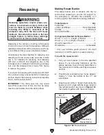
Page 54: ...will cause kickback Be certain that stock is flat and straight Failure to follow these warnings could result in serious personal injury 8 x 2 Wood Screw Assembled Resaw Barrier 3 4 3 4 Figure 102 Resa...

Page 55: ...therboards to keep your hands at a safe distance from the blade throughout the entire cut Always replace guard after completing the cut Rip Fence Table Resaw Barrier Workpiece Figure 103 Resaw setup 6...

Page 56: ...ximately 3 4 thick to size The length and width of the board can vary according to your design Most featherboards are 10 28 long and 3 6 wide Make sure the wood grain runs paral lel with the length of...

Page 57: ...he coun tersunk hole in the center then use a jig saw with a narrow blade to cut it out 8 Assemble the miter bar and featherboard with a 1 4 20 x flat head screw flat washer and a wing nut or a star k...

Page 58: ...e workpiece Mounting Featherboards w Clamps 4 Secure the featherboard to the table with a clamp 5 Check the featherboard by pushing it with your thumb to ensure it is secure If the featherboard moves...

Page 59: ...ck Push Stick Prohibition Zone Store Push Stick Here for Easy Access Supporting A second push stick can be used to keep the workpiece firmly against the fence while cutting When using a push stick in...

Page 60: ...ing a Push Block A push block can be used in place of or in addi tion to a push stick for feeding workpieces into the blade Due to their design push blocks allow the operator to apply firm downward pr...

Page 61: ...and push block system shown in this section is an example of a specialty jig that can be made to increase the safety of very narrow rip cuts 2 Pre drill and countersink eight pilot holes 3 8 from the...

Page 62: ...op before removing the cut off piece Failure to follow this warn ing could result in serious personal injury 3 Place the workpiece 1 behind the blade and evenly against the table and the auxiliary fen...

Page 63: ...minimize this risk only install accessories recommended for this machine by Grizzly NOTICE Refer to the newest copy of the Grizzly Catalog for other accessories available for this machine SECTION 6 AF...

Page 64: ...ry illnesses If you work around dust everyday a half mask respirator can be a lifesaver Also compatible with safety glasses Figure 129 Model H8003 Hydraulic Lifting Table H8003 Hydraulic Lifting Table...

Page 65: ...maintenance Failure to do this may result in serious person al injury The frequency of maintenance necessary for any machine will always depend on the operating con ditions and environment The schedul...

Page 66: ...s ALWAYS DISCONNECT POWER BEFORE DOING MAINTENANCE Lubricate the areas indicated below with general purpose grease every 6 12 months depending on frequency of use see Figure 131 Blade Angling Trunnion...

Page 67: ...rect voltage 4 Move blade guard to the working position replace faulty limit switch 5 Close door replace faulty safety switch 6 Correct motor wiring connections 7 Turn cut out dial to increase working...

Page 68: ...back 1 Sliding table is not parallel to blade 2 Riving knife is not aligned with the blade 3 Blade is warped 1 Make sliding table parallel to the blade Page 69 2 Shim the riving knife to align it wit...

Page 69: ...nsion controls Tension Bolt Lock Handle Pivot Handle Pulley Deflection Pulley Figure 133 Checking belt deflection The correct range of belt deflection for this machine is 1 4 1 2 If the belt deflectio...

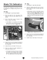
Page 70: ...it will go 3 Use a machinist s square to inspect if the blade is square to the table If the blade is not square to the table loosen the two set screws that secure the 90 tilt stop nut shown in Figure...

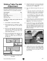
Page 71: ...ding table all the way forward and measure the dis tance between B in Figure 137 6 Note the difference between the two posi tions If the gap is the same on both sides or the difference is 0 004 or les...

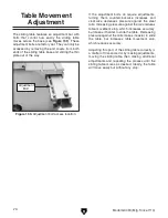
Page 72: ...re adjustments turning them counterclockwise increases and clockwise decreases pressure against the steel rails Increasing pressure against the rails reduces table movement slop which increases accura...

Page 73: ...n be done by using a piece of scrap plywood as a test piece and mak ing five test cuts then adjusting the fence as necessary To square the crosscut fence with the blade 1 Make sure the blade is parall...

Page 74: ...asily bend it back into alignment we recommend replacing it with a new one 6 Properly re install the spreader riving knife as described on Page 40 close the blade cover and move the sliding table back...

Page 75: ...k all wires dis connected or connected during any wiring task to ensure tight connections CIRCUIT REQUIREMENTS You MUST follow the requirements at the beginning of this man ual when connecting your ma...

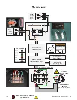
Page 76: ...1 2 24 23 Door Limit Switch 12 11 24 23 Blade Guard Limit Switch Main Motor see Page 60 Scoring Motor see Page 61 Control Panel see Page 59 Electrical Box see Pages 57 58 R S T 12 11 Ground Hot Hot H...

Page 77: ...U V W X Y Z U U V V W W R S T R R S S T T 0 6 5 4 3 7 8 1 2 STAR DELTA TIMER 24VAC TRD N 4 4 NC15 NC16 Ground R S T 5 0 1 7 To Power Connection Box To Control Panel To Main Motor To Scoring Motor 440V...

Page 78: ...U V W X Y Z U U V V W W R S T R R S S T T 0 6 5 4 3 7 8 1 2 STAR DELTA TIMER 24VAC TRD N 4 4 NC15 NC16 Ground R S T 5 0 1 7 To Power Connection Box To Control Panel To Main Motor To Scoring Motor 440V...

Page 79: ...TRICAL SAFETY ON PAGE 73 X1 X2 Power Light 22 21 13 14 Scoring Blade ON 22 21 13 14 22 21 13 14 22 21 13 14 Main Blade ON 22 21 13 14 Key Switch Main Blade OFF Scoring Blade OFF EMERGENCY STOP 1 0 1 7...

Page 80: ...ce 7 10 READ ELECTRICAL SAFETY ON PAGE 73 Ground 220V 12 U X 6 4 5 10 11 1 7 V Y 2 8 W Z 3 9 Ground 440V 12 U X 10 11 1 V Y 2 W Z 3 additional conversions required for 440V operation To Electrical Box...

Page 81: ...Model G0493 Mfg Since 7 10 79 READ ELECTRICAL SAFETY ON PAGE 73 Ground R S T 7 1 8 2 9 3 6 4 5 Ground R S T 1 2 3 additional conversions required for 440V operation 220V 440V 4 7 5 8 6 9 Scoring Motor...

Page 82: ...4930005 FLIP STOP 20 P04930020 ROTATE BLOCK 6 PSS01M SET SCREW M6 1 X 10 21 PS38M PHLP HD SCR M4 7 X 10 7 PLN05M LOCK NUT M10 1 5 22 PS25M PHLP HD SCR M4 7 X 35 8 P04930008 SQUARE TUBE 23 P04930023 FI...

Page 83: ...01 T NUT M8 1 25 124 PW01M FLAT WASHER 8MM 107 P04930107 KNOB SCREW M8 1 25 X 25 125 P04930125 KNOB SCREW M8 1 25 X 50 108 PW01M FLAT WASHER 8MM 126 PB26M HEX BOLT M8 1 25 X 30 109 P04930109 PLUG 38 X...

Page 84: ...63 242 243 268 237 248 249 250 222 207 228 229 230 217 215 216 221 218 219 220 214 257 256 241 227 233 201 202 238 239 240 244 246 247 245 267 264 269 231 251 266 265 203 204 233 205 208 210 211 212 2...

Page 85: ...ERGENCY STOP BUTTON E2R1R 1B 260 P04930260 POWER BOX 220 P04930220 CONTROL PANEL FACE 261 P04930261 TERMINAL 4P 221 PS17M PHLP HD SCR M4 7 X 6 262 PS05M PHLP HD SCR M5 8 X 8 222 P04930222 CORD 1C 263...

Page 86: ...MM 306A P04930306A CHANNEL BASE V2 08 07 320 PW02M FLAT WASHER 5MM 307 PW03M FLAT WASHER 6MM 321 P04930321 HINGE 308 PLW03M LOCK WASHER 6MM 322A P04930322A COVER V2 08 07 309 PSB04M CAP SCREW M6 1 X 1...

Page 87: ...1 P04930406 1 RIVING KNIFE 425 P6206 2RS BALL BEARING 6206 2RS 407 P04930407 LOCK PLATE 426 P04930426 MAIN HOUSING 408 PLW05M LOCK WASHER 12MM 427 P04930427 BEARING HOUSING 409 PN09M HEX NUT M12 1 75...

Page 88: ...10MM 515V2 PR02M EXT RETAINING RING 14MM 504 P04930504 T NUT M12 1 75 516V2 P04930516V2 SPRING V2 07 10 505A P04930505A KNOB SCREW M10 1 5 X 20 V2 10 07 517V2 P04930517V2 SHAFT V2 07 10 506A PW04M FLA...

Page 89: ...REW M10 1 5 X 20 627 PSB11M CAP SCREW M8 1 25 X 16 608 PLW06M LOCK WASHER 10MM 628 PLW04M LOCK WASHER 8MM 609 PSS04M SET SCREW M6 1 X 12 629 P04930629 END WASHER 610 P04930610 SMALL EXTENSION TABLE 63...

Page 90: ...30V2 PLASTIC BEARING V2 07 10 704 P04930704 KNOB SCREW M10 1 5 X 70 731 PW03M FLAT WASHER 6MM 706 P04930706 LOCATE PLATE 732V2 P04930732V2 CAP SCREW M6 1 X 10 V2 07 10 707 P04930707 MICRO ADJUST KNOB...

Page 91: ...834 833 832 831 830 801 802 812 813 819 829 828 815 816 818 851 850 849 848 847 857 856 858 821 804 820 817 860 861 862 863 864 871 872 876 875 874 866 865 867 868 869 870 873 859 878 877 880 881 882...

Page 92: ...30822 LOCATE PLATE 868 PSB106M CAP SCREW M8 1 25 X 90 823 PSB30M CAP SCREW M6 1 X 45 869 PK23M KEY 5 X 5 X 25 824 P04930824 LOCATE BUSHING 870 P04930870 MOTOR PULLEY 60HZ 825 P04930825 ADJUST SHAFT 87...

Page 93: ...905 904 903 902 901 906 909 910 911 912 914 917 919 920 921 922 923A 924 925 926A 930 931A 933 934 935 936 916 913 951A 937 932A 915 953A 955 918 929 928 950A 927 947 941 940 939 938 948 946 945A 944...

Page 94: ...R 6MM 913 P04930913 SCREW TR20 2 0 X 2T 941 PW03M FLAT WASHER 6MM 914 P04930914 SET NUT TR20 2 0 X 2T 942 P04930942 SLEEVE 915 P04930915 THRUST BEARING 10 X 12MM 943 PSB14M CAP SCREW M8 1 25 X 20 916...

Page 95: ...ARING 51102 1005 PSBS03M BUTTON HD CAP SCR M8 1 25 X 16 1022 PB82M HEX BOLT M8 1 25 X 80 1006 P04931006 MAGNETIC BRACKET 1023 PW01M FLAT WASHER 8MM 1007A P04931007A SLIDING TUBE V2 08 07 1024 PLN04M L...

Page 96: ...143A 1138 1134 1150 1149 1148 1153 1154 1152 1151 1161 1160 1142 1141 1140 1144 1145 1146 1162 1104 1163 1164 1120 1123 1124 1121 1126 1125 1127 1128 1159 1158 1157 1156 1155 1169 1168 1167 1166 1165...

Page 97: ...1 5 X 65 1164 P04931164 STRAIN RELIEF BG 04 1122 PN02M HEX NUT M10 1 5 1165 PB01M HEX BOLT M10 1 5 X 30 1123 PN02M HEX NUT M10 1 5 1166 PLW06M LOCK WASHER 10MM 1124 P04931124 FIXED BLOCK 1167 PW04M FL...

Page 98: ...PLATE V3 07 10 1226V3 P04931226V3 COVER V3 07 10 1246V3 PBHS09M BUTTON HD CAP SCR M6 1 X 12 1227 PFH26M FLAT HD SCR M6 1 X 30 1247V3 PCAP115M BUTTON HD CAP SCR M6 1 X 16 1228V3 P04931228V3 RUBBER BLO...

Page 99: ...14 P04510014 OL RELAY RA 20E 2 6 4 4A 1404 P04510004 OFF SWITCH BUTTON 1415 P04510015 LIMIT SWITCH 1405 P04510005 E STOP BUTTON 1416 P04510016 440V CONV KIT OLR RA 20 8 12A 1406 P04510006 TERMINAL 3 C...

Page 100: ...P04931502 UPPER BLADE GUARD LABEL 1514 P04931514 TRAINED PERSONNEL ONLY LABEL 1503 PLABEL 11 SAFETY GLASSES LABEL 1515 PPAINT 11 PUTTY COLOR TOUCH UP PAINT 1504 P04931504 LOOSEN TIGHTEN FENCE LABEL 1...

Page 101: ...metalworker ____ 0 2 Years ____ 2 8 Years ____ 8 20 Years ____20 Years 6 How many of your machines or tools are Grizzly ____ 0 2 ____ 3 5 ____ 6 9 ____10 7 Do you think your machine represents a good...

Page 102: ...LINE FOLD ALONG DOTTED LINE GRIZZLY INDUSTRIAL INC P O BOX 2069 BELLINGHAM WA 98227 2069 Place Stamp Here Name_______________________________ Street_______________________________ City______________S...

Page 103: ...tried in the State of Washington County of Whatcom We shall in no event be liable for death injuries to persons or property or for incidental contingent special or consequential damages arising from...

Page 104: ...Buy Direct and Save with Grizzly Trusted Proven and a Great Value Since 1983 ORDER 24 HOURS A DAY 1 800 523 4777 Visit Our Website Today For Current Specials...

Reviews: