G0516 Lathe/Mill
-25-
Understanding
Gear Charts
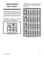
0.005" 0.010"
C B
D E
F
35 80
90 30
100
50 80
66 30
100
Figure 26.
Turning chart.
The Model G0516 can be geared for a variety of
different feed rates, so charts are placed on the
drive cover of the lathe that explain how to set up
the gear combinations for each type of carriage
feed application. These applications are broken
into two categories of charts—turning and thread-
ing.
Turning Chart
—The speeds given on the turning
chart represent standard speeds for most types
of turning applications. See
Figure 26
.
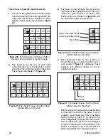
Figure 27.
Threading charts.
Threading Charts
—By arranging the gears as
shown on the charts, you can set up the carriage
feed to cut any of the thread pitches displayed.
See
Figure 27
.
1"
⁄
n
16
18
20
24
32
40
B
E
D
F
70
40
60
80
70
80
60
45
70
80
60
50
70
40
50
100
70
80
45
60
70
40
30
100
1"
⁄
n
8
9
10
11
12
14
B
E
D
F
80
40
75
50
90
40
60
45
70
40
72
60
70
40
72
66
70
72
40
70
40
60
70
1.25 1.5 1.75
2
2.5
3
B
D E
C
F
80
75
30
68
72
80
60
48
68
72
80
60
40
68
72
80
70
40
68
72
80
70
35
68
72
80
90
30
68
72
0.4
0.5
0.6
0.7
0.8
1
B
D E
C
F
80
48
60
68
72
80
30
75
68
72
80
35
70
68
72
80
45
75
68
72
40
35
100
68
72
80
68
60
72
mm
mm

