-26-
G0516 Lathe/Mill
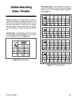
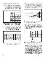
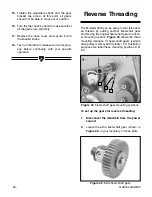
This is how to read the feed rate charts:
1.
The box in the upper left-hand corner of each
chart tells whether that chart represents car-
riage feed movement for standard or metric
threads. These boxes are shaded in
Figure
28
.
1"
⁄
n
16
18
20
24
B
E
D
F
70
40
60
80
70
80
60
45
70
80
60
50
70
40
50
100
0.4
0.5
0.6
0.7
B
D E
C
80
30
68
72
80
35
68
72
80
45
68
72
40
35
68
72
mm
Figure 28.
The shaded box indicates whether
the chart is for standard or metric threads.
1"
⁄
n
16
18
20
24
32
40
B
E
D
F
70
40
60
80
70
80
60
45
70
80
60
50
70
40
50
100
70
80
45
60
70
40
30
100
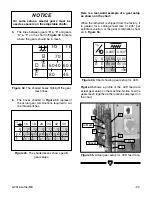
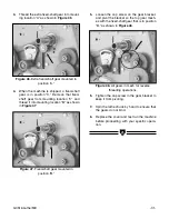
Figure 29.
The shaded boxes show the thread
pitches listed on this chart.
2.
The boxes in the top row of each chart
(excluding the box in the left-hand corner)
shows the thread pitches listed on that chart.
These boxes are shaded in
Figure 29
.
1"
⁄
n
16
B
E
D
F
70
40
60
80
Upper Adjustable Shaft
Lower Adjustable Shaft
Pivot Shaft
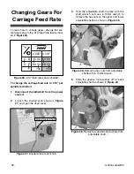
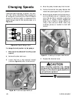
Figure 30.
The shaded boxes show the thread
pitches listed on this chart.
1"
⁄
n
16
18
20
24
B
E
D
F
70
40
60
80
70
80
60
45
70
80
60
50
70
40
50
100
Rear
Forward
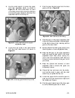
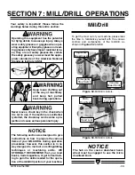
Figure 31.
The shaded boxes show the thread
pitches listed on this chart.
3.
The boxes on the left-hand column (exclud-
ing the box in the upper left-hand corner) rep-
resent the gear positions on each shaft.
These boxes are shaded in
Figure 30
and
the shafts are called out with arrows.
4.
Each shaft has room for two positions to
mount the gears—a forward position and a
rear position.
Figure 31
separates these
positions into different shades for you to
understand better.
Both forward and rear positions must be filled
on the shaft in order for the gears to work
properly. A good example of this is the blank
spot to the right of gear “F,” as shown in the
chart in
Figure 31
. Although the chart shows
this as a blank spot, there should actually be
a spacer in this position on the machine. This
spacer is not listed on the chart, because the
chart only reflects ACTIVE gear positions.

