G0532 2HP Dry Spray Booth
-19-
Air Filter Indicator
Components and Hardware Needed:
Qty
Air Filter Indicator (Manometer) ..........................1
Tubing Connector Fitting ....................................1
Tubing .................................................................2
Plastic Clip ..........................................................1
Tap Screw M4 x 12 .............................................1
Tap Screws M4 x 45 ...........................................2
To install the air filter indicator:
1.
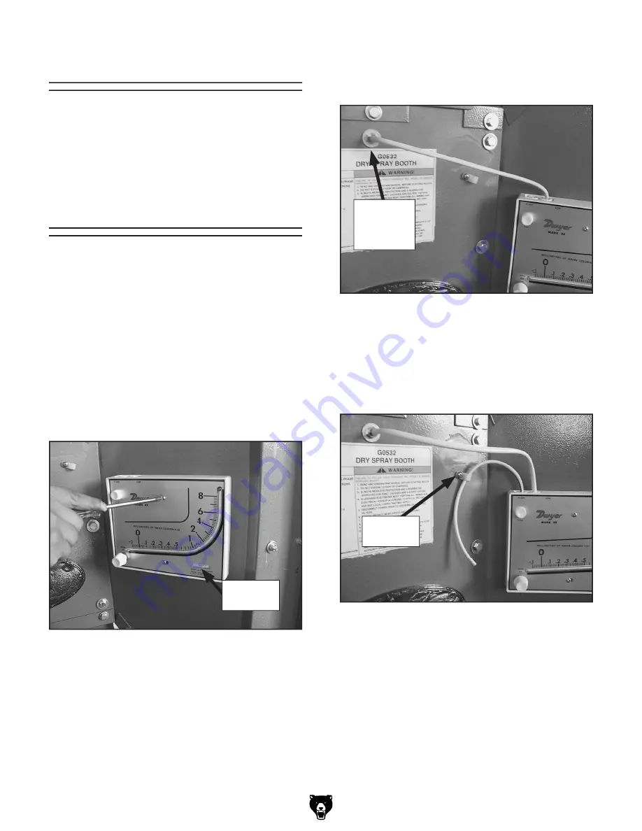
Mount the manometer to the side of the
spray booth using the M4 x 45 tap screws as
shown in
Figure 21
.
5.
Install tubing onto the high pressure side (+)
of the manometer and secure it with the plas-
tic clip and M4 x 12 tap screw as shown in
Figure 23
.
Figure 22.
Tubing installed onto spray booth
chamber.
2.
Adjust the manometer so the built-in level
reads level (
Figure 21
).
3.
Install a tubing connector fitting in the larger
pre-drilled hole on the side of the booth near
the manometer as shown in
Figure 22
.
4.
Run tubing from the low pressure side (-) of
the manometer to the tubing connector fitting
as shown in
Figure 22
.
Figure 21.
Mounting manometer to spray booth.
Figure 23.
Tubing secured with clip.
Ducting
The G0532 dry spray booth must be vented to
the outside of your shop or building using 10"
metal spiral wound ducting or 18 gauge rolled
galvanized steel ducts in accordance with NFPA
33 guidelines.
Tubing
Connector
Fitting
Plastic
Clip
Built-in
Level
Summary of Contents for G0532
Page 5: ...G0532 2HP Dry Spray Booth 3 Data Sheet ...
Page 6: ... 4 G0532 2HP Dry Spray Booth ...
Page 14: ... 12 G0532 2HP Dry Spray Booth Hardware Recognition Chart ...
Page 26: ... 24 G0532 2HP Dry Spray Booth 115V Wiring Diagram ...
Page 27: ...G0532 2HP Dry Spray Booth 25 230V Wiring Diagram ...
Page 28: ... 26 G0532 2HP Dry Spray Booth Parts Breakdown ...
Page 32: ... 30 G0532 2HP Dry Spray Booth ...
Page 35: ......


