


-10-
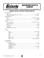
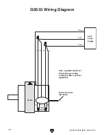
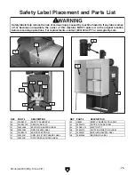
Model g0533 (Mfg. since 3/11)
SEcTiON 3: SET UP
the following items are needed to complete the
set up process, but are not included with your
machine:
DEScRiPTiON
Qty
•
assistants ....................................................2
•
hoist ............................................................1
•
safety glasses (for each person) ................1
•
phillips head screwdriver............................1
•
open-end Wrench
7
⁄
16
" ................................1
•
open-end Wrench
1
⁄
2
" .................................1
•
ducting (length as needed,
Page 16) .........1
•
switch and Wiring ..... (as per nFpa 33 and
neC regulations)
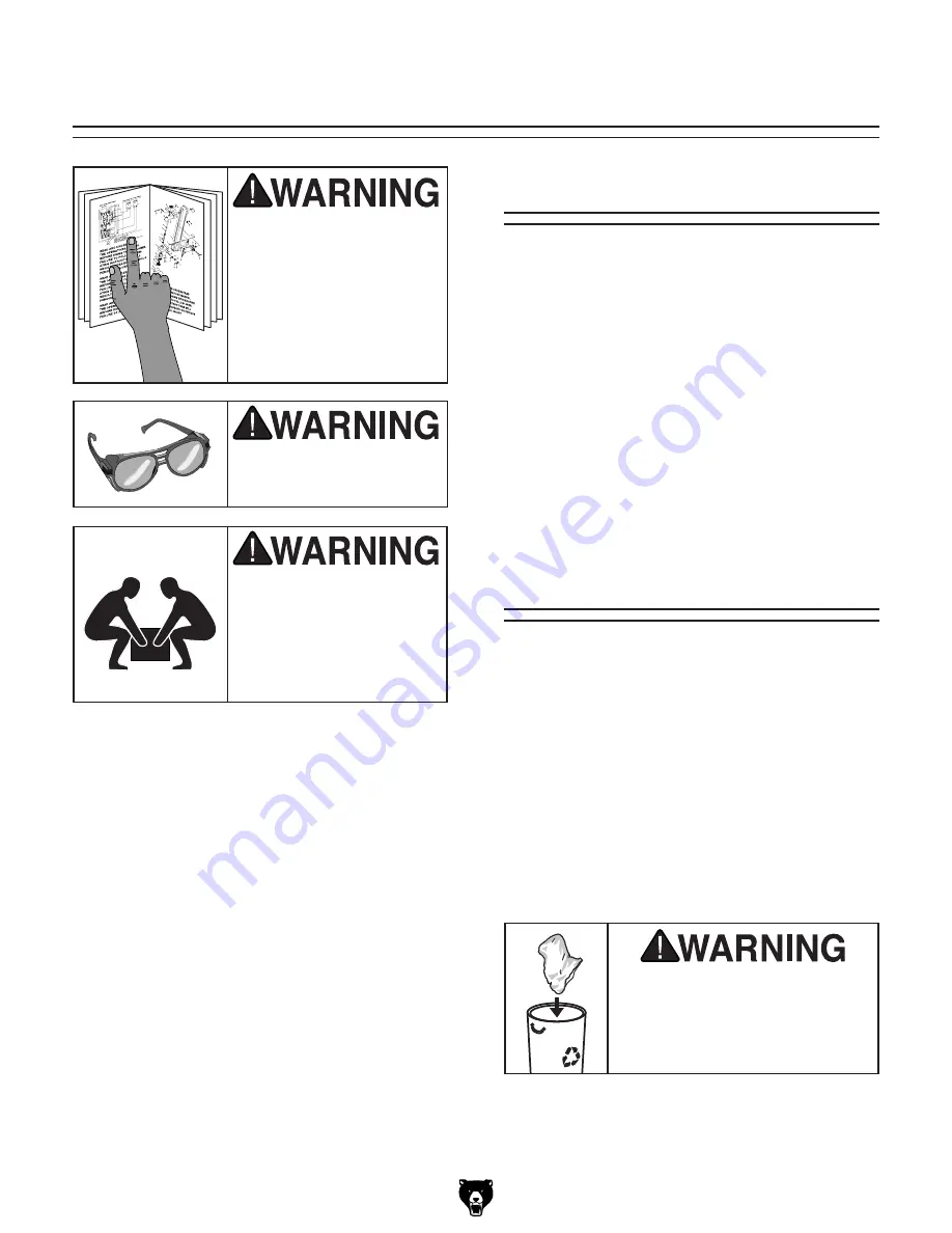
Needed for Set Up
This machine presents
serious injury hazards
to untrained users. Read
through this entire manu-
al to become familiar with
the controls and opera-
tions before starting the
machine!
Wear safety glasses dur-
ing the entire setup pro-
cess!
This machine and its com-
ponents are very heavy.
Get lifting help or use
power lifting equipment
such as a forklift to move
heavy items.
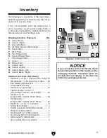
your machine was carefully packaged for safe
transportation. remove the packaging materials
from around your machine and inspect it. if you
discover the machine is damaged,
please imme-
diately call Customer Service at (570) 546-9663
for advice.
save the containers and all packing materials for
possible inspection by the carrier or its agent.
Otherwise, filing a freight claim can be difficult.
When you are completely satisfied with the condi-
tion of your shipment, inventory the contents.
Unpacking
SUFFOCATION HAZARD!
Keep children and pets away
from plastic bags or packing
materials unpacked with this
machine. Discard immediately.
Summary of Contents for G0533
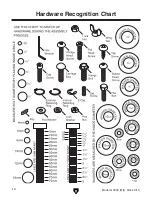
Page 14: ... 12 Model G0533 Mfg Since 3 11 Hardware Recognition Chart ...
Page 28: ... 26 Model G0533 Mfg Since 3 11 ...
Page 31: ......


