


Model g0533 (Mfg. since 3/11)
-13-
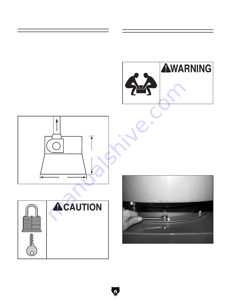
To install the exhaust fan housing:
1. place the inlet gasket over the exhaust fan
inlet.
Exhaust fan
floor Load
Refer to the
Machine Data Sheet
for the weight
and footprint specifications of your machine.
Some floors may require additional reinforcement
to support both the machine and operator.
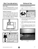
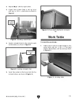
Working clearances
Consider existing and future needs, size of mate-
rial to be processed through each machine, and
space for auxiliary stands, work tables or other
machinery when establishing a location for your
new machine. Make a note of the exhaust fan
location. (See
Safety
on
Page 8
.) See
figure 3
for the minimum working clearances.
Unsupervised children and
visitors inside your shop
could cause serious per-
sonal injury to themselves.
Lock all entrances to the
shop when you are away and
DO NOT allow unsupervised
children or visitors in your
shop at any time!
Site considerations
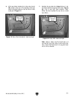
figure 3.
Minimum working clearances (top
view).
52"
63"
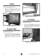
The exhaust fan is very
heavy. You MUST have
assistance when mov-
ing, lifting or mounting
the exhaust fan onto the
spray booth.
2. With the help of two strong assistants, or
using a hoist,
place the exhaust fan housing
over the inlet gasket.
3. rotate the exhaust fan housing so the outlet
port is aimed toward the back of the spray
booth.
4.
Align the gasket and exhaust fan mount-
ing holes,
and
fasten with eight
5
⁄
16
"-18 x
1" hex bolts and flat washers, as shown in
figure 4
.
figure 4. installing exhaust fan onto spray
booth.
Summary of Contents for G0533
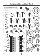
Page 14: ... 12 Model G0533 Mfg Since 3 11 Hardware Recognition Chart ...
Page 28: ... 26 Model G0533 Mfg Since 3 11 ...
Page 31: ......


