G0555LX
(Mfg. Since 3/13)
-17-
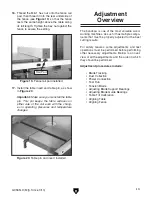
4. Turn the stand assembly upright and attach
the top, as shown in
Figure 11, with (8)
5
⁄
16
"-
18 x
5
⁄
8
" carriage bolts and (8)
5
⁄
16
"-18 flange
nuts.
Figure 11. Stand top attached.
x 8
5. Square up the stand components and fully
tighten all the fasteners.
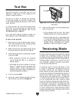
6. Place the level on top of the stand assembly,
as shown in
Figure 12, then adjust the feet
up or down to make the stand top level from
side to side and front to back. Make sure that
both hex nuts on the feet are tight against the
stand assembly so they will not move.
Figure 12. Leveling the stand.
7. With the help of other people, lift the bandsaw
assembly onto the stand and align the mount-
ing holes. Have one person hold the bandsaw
in place to keep it from fall until you can com-
plete the next step.
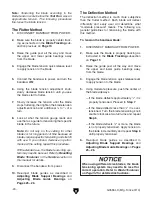
8. Secure the bandsaw assembly to the stand
with (4)
5
⁄
16
"-18 x 1
1
⁄
2
" hex bolts, (4)
5
⁄
16
" lock
washers, (8)
5
⁄
16
" flat washers, and (4)
5
⁄
16
"-18
hex nuts, as shown in
Figure 13.
Figure 13. Bandsaw assembly attached to the
stand.
x 4
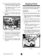
9. Position the table trunnion on the bandsaw,
as shown in
Figure 14, then secure it with the
(2)
5
⁄
16
"-18 x 1
1
⁄
4
" hex bolts and (2)
5
⁄
16
" lock
washers.
Figure 14. Trunnion installed.
x 2
Trunnion
Summary of Contents for G0555LA35
Page 12: ...12 Model G0555LA35 Mfd Since 11 17...
Page 80: ......

