G0600 20" x 60" Big Bore Lathe
-23-
Apron and Spindle
Break-in
It is essential to closely follow the proper break-in
procedures to ensure trouble free performance.
Complete this process once you have familiarized
yourself with all instructions in this manual and
completed the test run.
To break-in the spindle:
1.
Make sure that the headstock, gearbox,
apron, and lead screw and feed rod oil bath
oil levels show full. Follow all lubrication
procedures highlighted in
Lubrication
in the
MAINTENANCE
section on
Page 51
of this
manual.
2.
Make sure there are no obstructions around
or underneath the chuck and that the chuck
is secured to the spindle. Refer to
Chuck and
Faceplate Mounting
on
Page 24
.
3.
Set the spindle speed to the lowest RPM;
refer to section
Setting RPM
on
Page 35
.
4.
Move the headstock and gearbox levers so
the feedrod and leadscrew are engaged.
Refer to section
Using the Thread Cart
on
Page 40
for lever combinations.
5.
Make sure that the halfnut lever is disen-
gaged, and that the apron and cross feed
feed lever is in neutral. Refer to section
Power Feed
on
Page 37
for lever combina-
tions.
6.
Turn the lathe
ON
and let it run for a minimum
of 10 minutes.
7.
Turn the lathe
OFF
, shift the levers to the
next highest RPM and repeat
Steps 5-6
for
each RPM setting in both directions. DO NOT
LEAVE THE AREA!
Failure to follow beak-in procedures will
likely cause rapid deterioration of bearings
and other related parts.
NOTICE
Spindle Balancing
After the spindle has been broken in, or if the lathe
has been used for a considerable amount of time,
you should adjust the spindle weights to minimize
spindle vibration.
To minimize spindle vibration:
1.
Run the lathe for five minutes on the fastest
RPM.
2.
DISCONNECT LATHE FROM POWER!
3.
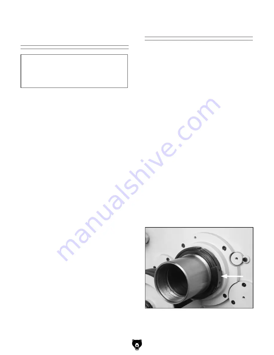
Open the side cover, loosen the counter
weight set screws (
Figure 14
), and reposition
one or both counterweights to a new posi-
tion around the circumference of the spanner
nut.
4.
Close the side cover, reconnect to power,
restart the lathe, and run at 1600 RPM.
5.
Place your hand on the headstock cover and
feel for harmonic vibration.
6.
Repeat
Steps 2
through
5
until any vibration
is reduced to its minimum.
7.
Now, repeat
Steps 2
through
5
at 1100 RPM
until any vibration is reduced to its minimum.
Figure 14
. Spindle counterweights.
Summary of Contents for G0600
Page 3: ... ...
Page 8: ...G0600 20 x 60 Big Bore Lathe 5 ...
Page 9: ... 6 G0600 20 x 60 Big Bore Lathe ...
Page 12: ...G0600 20 x 60 Big Bore Lathe 9 SECTION 1 SAFETY ...
Page 13: ... 10 G0600 20 x 60 Big Bore Lathe ...
Page 19: ... 16 G0600 20 x 60 Big Bore Lathe Hardware Recognition Chart ...
Page 72: ...G0600 20 x 60 Big Bore Lathe 69 Headstock Face and Shift System 0000 Series Parts ...
Page 73: ... 70 G0600 20 x 60 Big Bore Lathe Headstock Shift System 0000 Series Parts ...
Page 74: ...G0600 20 x 60 Big Bore Lathe 71 Headstock Oil Pump System 0000 Series Parts ...
Page 78: ...G0600 20 x 60 Big Bore Lathe 75 Quick Change Gearbox Gear System 1000 Series Series Parts ...
Page 79: ... 76 G0600 20 x 60 Big Bore Lathe Quick Change Gearbox Face 1000 Series Parts ...
Page 80: ...G0600 20 x 60 Big Bore Lathe 77 Quick Change Gearbox Shift System 1000 Series Parts ...
Page 81: ... 78 G0600 20 x 60 Big Bore Lathe Quick Change Gearbox Shift System 1000 Series Parts ...
Page 84: ...G0600 20 x 60 Big Bore Lathe 81 Carriage 2000 Series Parts ...
Page 85: ... 82 G0600 20 x 60 Big Bore Lathe Cross Slide and Carriage 2000 Series Parts ...
Page 86: ...G0600 20 x 60 Big Bore Lathe 83 Compound Rest and Tool Post 2000 Series Parts ...
Page 87: ... 84 G0600 20 x 60 Big Bore Lathe Carriage Oil Pump System 2000 Series Parts ...
Page 90: ...G0600 20 x 60 Big Bore Lathe 87 Apron Face Thread Dial Auto Stop System 3000 Series Parts ...
Page 91: ... 88 G0600 20 x 60 Big Bore Lathe Apron Gearing Halfnut Feed System 3000 Series Parts ...
Page 92: ...G0600 20 x 60 Big Bore Lathe 89 Apron Feed Rod Clutch and Lever System 3000 Series Parts ...
Page 95: ... 92 G0600 20 x 60 Big Bore Lathe Tailstock 4000 Series Parts ...
Page 97: ... 94 G0600 20 x 60 Big Bore Lathe Bed Assembly 5000 Series Parts ...
Page 98: ...G0600 20 x 60 Big Bore Lathe 95 Brake Pedal and Headstock Panels 5000 Series Parts ...
Page 99: ... 96 G0600 20 x 60 Big Bore Lathe Brake System and Change Gears 5000 Series Parts ...
Page 100: ...G0600 20 x 60 Big Bore Lathe 97 Motor and Headstock Mounting 5000 Series Parts ...
Page 101: ... 98 G0600 20 x 60 Big Bore Lathe End Covers and Splash Guard 5000 Series Parts ...
Page 102: ...G0600 20 x 60 Big Bore Lathe 99 Change Gear System 5000 Series Parts ...
Page 105: ... 102 G0600 20 x 60 Big Bore Lathe Steady and Follow Rests 6000 Series Parts ...
Page 110: ... ...
Page 111: ... ...
Page 112: ......
Page 113: ... ...


