background image

Model g0636XB

-7-

220v single-phase

full load amperage draw

this  machine  draws  the  following  amps  under 
maximum load:

amp draw ..............................................22 amps

power supply circuit requirements

you Must connect your machine to a grounded 
circuit that is rated for the amperage given below. 
never replace a circuit breaker on an existing cir-
cuit with one of higher amperage without consult-
ing  a  qualified  electrician  to  ensure  compliance 
with wiring codes. 

if you are unsure about the 

wiring codes in your area or you plan to con-

nect your machine to a shared circuit, consult 

a qualified electrician.

Minimum Circuit size .............................30 amps

extension cords

using extension cords may reduce the life of the 
motor.  instead,  place  the  machine  near  a  power 
source. if you must use an extension cord:

• 

use  at  least  a  10  gauge  cord  that  does  not 
exceed 50 feet in length!

• 

the extension cord must also have a ground 
wire and plug pin.

• 

a qualified electrician Must size cords over 
50 feet long to prevent motor damage.

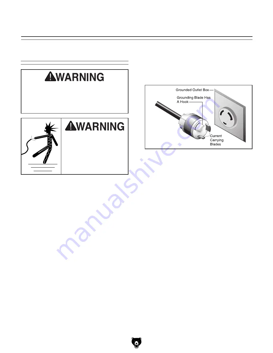
figure 

11

. neMa l6-30 plug and receptacle.

section 2: circuit reQuirements

serious  personal  injury  could  occur  if  you 

connect the machine to power before com-

pleting the setup process. do not connect 

the  machine  to  the  power  until  instructed 

later in this manual.

electrocution or fire could 

result  if  machine  is  not 

grounded  and  installed  in 

compliance with electrical 

codes.  compliance  must 

be  verified  by  a  qualified 

electrician!

power connection device

the type of plug required to connect your machine 
to power depends on the type of service you cur-
rently  have  or  plan  to  install.  We  recommend 
using the plug shown in 

figure 

11

.

Summary of Contents for G0636XB

Page 1: ...3 or email techsupport grizzly com MODEL G0636XB ULTIMATE 17 BANDSAW w MOTOR BRAKE Manual Insert Machine Inventory After all the parts have been removed from the crate you should have the following items Crate Contents Figure 1 Qty A Bandsaw not shown 1 B Miter Gauge 1 C Fence 1 D Resaw Fence 1 E Guide Post Handwheel 1 Figure 1 G0636XB inventory B C E D Hardware and Tools not shown Qty Hex Wrench ...

Page 2: ... further Always disconnect the machine from power when investigating or correcting potential problems 3 Press the OFF button to stop the machine 4 WITHOUT resetting the OFF button press the ON button The machine should not start If the machine does not start the OFF but ton safety feature is working correctly If the machine does start with the OFF button pushed in immediately disconnect power to t...

Page 3: ...age 25 5 Tighten the knobs and cap screw that secure the rail to the table being careful not to move the fence Figure 7 Example of fence square with miter slot 7 Try to turn the machine ON If the bandsaw does not start the switch disabling feature is working as designed The Test Run is complete If the bandsaw starts immediately discon nect power The switch disabling feature is not working correctl...

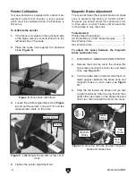
Page 4: ...is preset by the factory at 0 2mm 0 008 However you should adjust this space every two to three years or when it takes over five seconds for the brake to stop the motor Tools Needed Phillips Head Screwdriver 1 US Dollar Bills or 0 008 Feeler Gauges 2 Hex Wrench 3mm 1 Hex Wrench 4mm 1 To adjust the space between the magnetic brake and brake shoe 1 DISCONNECT BANDSAW FROM POWER 2 Remove the motor fa...

Page 5: ... Z K GZXdbbZcYZY 8 gXj i H oZ Vbe GZXdbbZcYZY Eaj IneZ A Eaj cXajYZY Cd Motor IneZ I 8 8VeVX idg HiVgi cYjXi dc dghZedlZg E KdaiV Z K E VhZ H c aZ 6beh 6 HeZZY GEB 8nXaZ o CjbWZg D HeZZYh EdlZg IgVch Zg 7Zai 9g kZ 7ZVg c h H ZaYZY VcY EZgbVcZcian AjWg XViZY 7gV Z 7j ai c BV cZi X IneZ K98 Main Specifications Operation Information 7aVYZ HeZZY EB IVWaZ I ai AZ i G i Cutting Capacities BVm bjb 8jii c...

Page 6: ...ZZa EV ci EdlYZg 8dViZY Other Specifications 8djcign D Dg c IV lVc LVggVcin NZVg HZg Va CjbWZg AdXVi dc 9 AVWZa dc JeeZg L ZZa 8dkZg 6hhZbWan HZije I bZ djg Features 8Vhi gdc IVWaZ Igjcc dc 7Vaa 7ZVg c 7aVYZ j YZh Fj X 8 Vc Z 7aVYZ GZaZVhZ IZch dcZg B Xgd 6Y_jhi c GVX E c dc IVWaZ I ai GVX E c dc JeeZg 7aVYZ j YZ Z i 6Y_jhibZci 8dbejiZg 7VaVcXZY 8Vhi gdc L ZZah l i g ooan 7ZVg ZVY 8ji Djih 7aVYZ I...

Page 7: ...ine near a power source If you must use an extension cord Use at least a 10 gauge cord that does not exceed 50 feet in length The extension cord must also have a ground wire and plug pin A qualified electrician MUST size cords over 50 feet long to prevent motor damage Figure 11 NEMA L6 30 plug and receptacle SECTION 2 CIRCUIT REQUIREMENTS Serious personal injury could occur if you connect the mach...

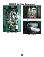
Page 8: ...Model G0636XB 8 G0636XB Electrical Components Figure 12 Magnetic switch Figure 13 Junction box wiring Figure 14 Capacitors ...

Page 9: ...rizzly com A B I HL I8 K BDIDG C8 H9 B6 K EDL G HJEEAN JC8I DC 7AD8 gdjcY N AADL L6 30 PLUG as recommended GZXi Zg EJ BV cZi X 7gV Z NO The motor wiring shown here is current at the time of printing but it may not match your machine Always use the wiring diagram inside the motor junction box G X Y gdjcY di di 220 VAC Gjc 8VeVX idg B 9 K68 HiVgi 8VeVX idg B 9 K68 H9 G6 See Figure 12 See Figures 13 ...

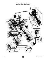
Page 10: ...Model G0636XB 10 Main Breakdown ...

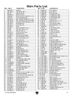
Page 11: ...OCK 78 PFS11M FLANGE SCREW M6 1 X 10 28 P51201 THRUST BEARING 51201 79 PB10M HEX BOLT M6 1 X 25 29 P0636X029 BLADE TENSION SHAFT 80 P0636X080B BRUSH 30 P0636X030 TENSION LINE 81 P0636XB081 STEP COVER 31 P0636X031 UPPER WHEEL SHAFT 85 PN04M HEX NUT M4 7 32 P0636XB032 UPPER WHEEL ASSEMBLY 94 P0531B023 MAG BRAKE MOTOR 5HP 220V 1PH 32 1 P0636X034 BUSHING 94 2 P0531B023 2 MOTOR FAN COVER 32 2 PR64M INT...

Page 12: ...080 2 RELAY SDE RA 30 18 26 112 PFS10M FLANGE SCREW M4 7 X 35 103 4 P0531B080 3 MAG SWITCH FRONT COVER 113 PS38M PHLP HD SCR M4 7 X 10 103 5 P0531B080 4 CORD 0 75MM X 5C 114 P0636X114V2 UPPER WHEEL COVER V2 06 08 103 6 P0636XB103 6 POWER CORD 12AWG X 3C 115 P0636X115 LOWER WHEEL COVER 103 7 P0636XB103 7 MOTOR CORD 12AWG X 5C 116 P0636X116 SAW BLADE 3TPI 162 X 1 X 0 035 103 8 PFS07M FLANGE SCREW M5...

Page 13: ...Model G0636XB 13 Table Fence Trunnion Breakdown ...

Page 14: ... 137 P0636X137 GUARD RAIL 160 4 P0513X2B152 4 POINTER 138 P0636X138 GUARD RAIL PLATE 160 5 PS06 PHLP HD SCR 10 24 X 3 8 139 PW01M FLAT WASHER 8MM 160 6 P0513X2B152 6 SHOULDER SCREW 140 PLW04M LOCK WASHER 8MM 160 7 P0513X2B152 7 MITER GAUGE BODY 141 PSB14M CAP SCREW M8 1 25 X 20 160 8 PW01M FLAT WASHER 8MM 142 PSB72M CAP SCREW M10 1 5 X 30 160 9 P0513X2B152 9 HANDLE 143 PLW06M LOCK WASHER 10MM 160 ...

Page 15: ... 7 PR03M EXT RETAINING RING 12MM 168 8 P0636X176 FIXED PLATE 172 8 P6201 BALL BEARING 6201ZZ 168 9 P0636X177 FIXED BOLT 172 9 P0636X249 UPPER SPACING SLEEVE 168 10 P0636X178 COVER 172 10 P0636X240 UPPER BLADE GUIDE SUPPORT 168 11 PLW04M LOCK WASHER 8MM 172 11 P0636X239 SHAFT 168 12 PB06M HEX BOLT M8 1 25 X 12 172 12 P0636X238 LOWER SUPPORT BRACKET 168 13 PFH19M FLAT HD SCR M4 7 X 10 172 13 PB83M H...

Page 16: ...ASSEMBLY DIRECTION LABEL 301 P0636XB301 MACHINE ID LABEL 311 G8589 GRIZZLY NAMEPLATE LARGE 302 PLABEL 11 SAFETY GLASSES LABEL 312 P0636X312 TENSION ADJ LABEL 303 PLABEL 12 READ MANUAL LABEL 313 P0636X313 TABLE ANGLE SCALE 304 PLABEL 14 ELECTRICITY LABEL 314 P0636X314 TABLE LOCK LEVER LABEL 305 PPAINT 1 GRIZZLY GREEN PAINT 316 P0636X316B MOTOR LABEL 306 PPAINT 11 GREY PUTTY TOUCH UP PAINT 317 P0636...

Reviews: