-18-
Model G0654 (Mfg. Since 9/07)
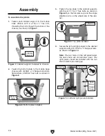
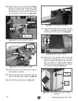
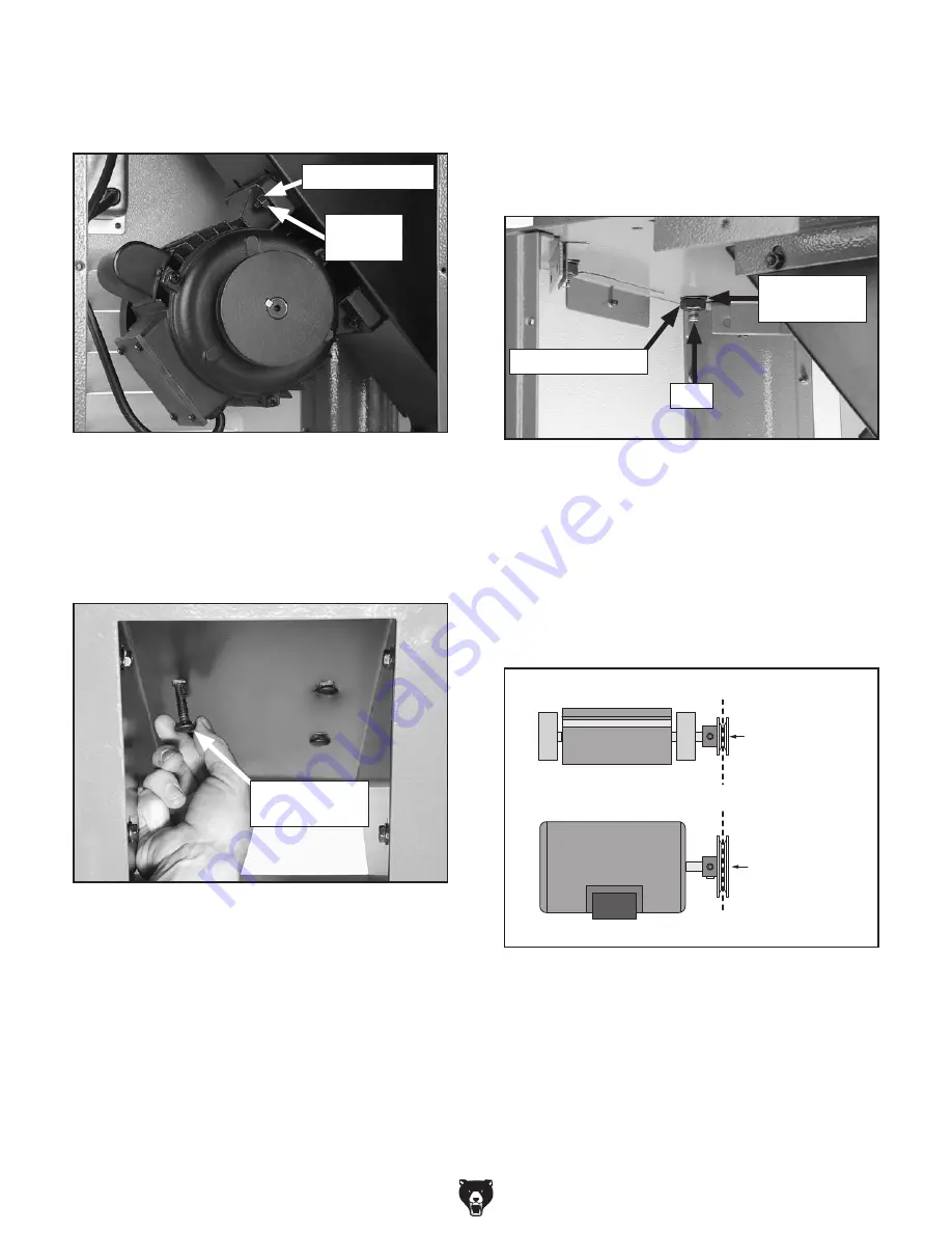
9. place the motor on the dust chute and align
the mounting holes, making sure the pulley
faces the v-belt slot (
figure 15).
figure 15. motor mounted to dust chute.
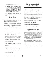
figure 16. securing motor to dust chute.
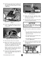
11. place the stand in the upright position and
adjust the leveling feet as needed with the
hex nuts so the cabinet rests level and stable
on the floor.
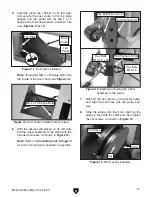
12. With the help of an assistant, place the jointer
table assembly on top of the cabinet assem-
bly, sliding the studs on the bottom of the
jointer table through the cabinet mounting
holes.
13. Fasten the jointer table assembly to the cabi-
net with the (3) m10-1.5 hex nuts and 10mm
lock washers, as shown in
figure 17.
Note: Reach inside the dust chute to secure
the stud on the right side.
figure 17. Jointer secured to cabinet.
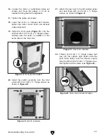
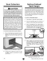
14. slide the motor up, place the v-belt around
the cutterhead and motor pulleys, then slide
the motor down to rest on the v-belt.
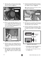
15. Check the alignment of the pulleys to make
sure that they are aligned and that the v-belt
is straight up and down, as shown in
figure
18.
Carriage Bolt
5
⁄
16
"-18 x 1
1
⁄
8
"
hex nut m10-1.5
stud
5
⁄
16
-18
hex nut
Flat Washer
5
⁄
16
"
lock Washer
10mm
figure 18. pulleys aligned.
Cutterhead
Pulley
Motor
Pulley
Alignment
— if the pulleys are aligned, then tighten the
motor fasteners and go to
Step 19.
— if the pulleys are not aligned, then per-
form
Steps 16-18.
10. reach into the dust chute, thread (4)
5
⁄
16
"-18
x 1
1
⁄
8
" carriage bolts through the chute and
motor and secure with (4)
5
⁄
16
"-18 hex nuts
and
5
⁄
16
" flat washers (see
figure 16). do not
fully tighten the fasteners.
Summary of Contents for G0654
Page 56: ......

