-26-
Model g0661/g0713 (Mfg. since 1/10)
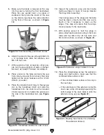
Figure 23. Front rail installed on saw.
Figure 24. rear rail installed on saw.
13. install the front rail with six M8-1.25 x 25
flat head screws, 8mm lock washers, and
M8-1.25 hex nuts, as shown in
Figure 23.
14. install the rear rail with six M8-1.25 x 25
flange cap screws, 8mm flat washers, and
M8-1.25 hex nuts, as shown in
Figure 24.
— if the outside end of the extension wing
tilts up, use a strip of masking tape along
the top edge of the main table to shim the
extension wing down (see
Figure 22).
Note:
After reinstalling wings, remove all
excess masking tape with a razor blade.
Figure 22. Masking tape location for shimming
the extension wing down.
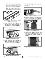
15. install the fence tube on the front rail with
six M8-1.25 x 10 flange bolts, as shown in
Figure 25.
Figure 25. Fence tube installed on front rail.
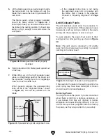
Figure 27. Motor cover installed on saw.
17. install the motor cover by sliding the hinge
posts into the hinges and locking the motor
cover closed with the knob, as shown in
Figure 27.
16. attach the switch to the front rail with two
M6-1 x 12 hex bolts, as shown in
Figure 26.
Figure 26. switch attached to rails.
x 6
x 6
x 6


