background image

-82-

Model g0661/g0713 (Mfg. since 1/10)

REF

PART #

DESCRIPTION

82

P0661082

MOTOR 2HP 110/220V 1-PH

82-1

PK34M

KEY 5 X 5 X 20

82-2

PSS20M

SET SCREW M8-1.25 X 8

82-3

P0661082-3

MOTOR PULLEY

82-4

P0661082-4

STRAIN RELIEF

82-5

P0661082-5

JUNCTION BOX

82-6

P0661082-6

MOTOR FAN COVER

82-7

P0661082-7

MOTOR FAN

82-8

P0661082-8

CAPACITOR COVER

82-9

P0661082-9

S CAP 200M 250V 1-1/2 X 2-3/4

82-10

P0661082-10

R CAP 30M 350V 1-1/2 X 2-3/4

REF

PART #

DESCRIPTION

82

P0713082

MOTOR 1-3/4 HP 110/220V 1-PH

82-1

PK34M

KEY 5 X 5 X 20

82-2

PSS20M

SET SCREW M8-1.25 X 8

82-3

P0661082-3

MOTOR PULLEY

82-4

P0661082-4

STRAIN RELIEF

82-5

P0661082-5

JUNCTION BOX

82-6

P0661082-6

MOTOR FAN COVER

82-7

P0661082-7

MOTOR FAN

82-8

P0661082-8

CAPACITOR COVER

82-9

P0661082-9

S CAP 200M 250V 1-1/2 X 2-3/4

82-10

P0661082-10

R CAP 30M 350V 1-1/2 X 2-3/4

G0661 2hp MOTOR

G0713 1-3/4 hp MOTOR

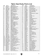
Table Saw Body parts List Continued

REF

PART #

DESCRIPTION

REF

PART #

DESCRIPTION

118-1V2 P0661118-1V2 DADO TABLE INSERT V2.01.10

135

P0661135

PUSH STICK HOLDER

118-2V2 PSS53M

SET SCREW M5-.8 X 12

141

P0661141

PUSH STICK

119

PAW05M

HEX WRENCH 5MM

145

PSS53M

SET SCREW M5-.8 X 12

120

PAW02.5M

HEX WRENCH 2.5MM

REF

PART #

DESCRIPTION

REF

PART #

DESCRIPTION

118-1V2 P0661118-1V2 DADO TABLE INSERT V2.01.10

135

P0661135

PUSH STICK HOLDER

118-2V2 PSS53M

SET SCREW M5-.8 X 12

141

P0661141

PUSH STICK

119

PAW05M

HEX WRENCH 5MM

145

PSS53M

SET SCREW M5-.8 X 12

120

PAW02.5M

HEX WRENCH 2.5MM

Summary of Contents for G0661

Page 1: ...manual keep it with the owner s manual for future reference If you have any further questions about this manual update or the changes made to the machine contact our Technical Support at 570 546 9663...

Page 2: ...As Recommended 220V 110V G Thermal Circuit Breaker Start Capacitor 200M 125V Run Capacitor 35M 300V Ground Ground 1 1 3 3 2 2 4 4 The motor wiring shown here is current at the time of printing however...

Page 3: ...nual Keep this update for future reference If you have any further questions about this manual update or the changes made to the machine contact our Technical Support at 570 546 9663 or email techsupp...

Page 4: ...WNER S Manual Copyright july 2010 By Grizzly Industrial Inc Warning No portion of this manual may be reproduced in any shape Or form without the written approval of Grizzly Industrial inc FOR MACHINES...

Page 5: ...ERSONAL PROTECTIVE EQUIPMENT 4HE MANUFACTURER WILL NOT BE HELD LIABLE FOR INJURY OR PROPERTY DAMAGE FROM NEGLIGENCE IMPROPER TRAINING MACHINE MODIFICATIONS OR MISUSE 3OME DUST CREATED BY POWER SANDING...

Page 6: ...llation 36 Blade Guard Assembly 37 Riving Knife 40 Cutting a Zero Clearance Insert 41 Ripping 42 Crosscutting 43 Miter Cuts 43 Blade Tilt Bevel Cuts 44 Dado Cutting 44 Rabbet Cutting 47 Resawing 49 SE...

Page 7: ...dgi dg Zae 7Z dgZ XVaa c cY i Z bVcj VXijgZ YViZ d ndjg bVX cZ Wn add c Vi i Z YViZ hiVbeZY cid i Z bVX cZ 9 aVWZa hZZ WZadl I h l aa Zae jh YZiZgb cZ i Z bVcjVa kZgh dc ndj gZXZ kZY bViX Zh i Z bVcj...

Page 8: ...Operating Saw a Wear eye protection b Use saw blade guard and spreader for every operation for which it can be used including all through sawing c Keep hands out of the line of saw blade d Use a push...

Page 9: ...ype Cardboard Content Machine Weight 288 lbs Length Width Height 33 x 31 x 22 in Carton 2 Type Cardboard Content Fence Weight 18 lbs Length Width Height 38 x 17 x 8 in Carton 3 Type Cardboard Content...

Page 10: ...loor To Table Height 35 3 8 in Table Size Width 20 in Table Size Depth 27 in Table Size Thickness 1 1 2 in Table Size With Extension Wings Width 44 in Table Size With Extension Wings Depth 27 in Table...

Page 11: ...ust Port Size 2 1 2 in Mobile Base G7314Z Other Specifications ISO Factory ISO 9001 Country Of Origin China Warranty 1 Year Serial Number Location ID Label on Cabinet Assembly Time 1 hour Features Riv...

Page 12: ...ZcXZ LZ i aWh AZc i L Yi Z i m m Carton 3 IneZ 8VgYWdVgY 8dciZci GV a LZ i aWh AZc i L Yi Z i m m Electrical EdlZg GZfj gZbZci K dg K H c aZ E VhZ o Hl iX DC D Ejh 7jiidc l i AdX dji E c Hl iX KdaiV...

Page 13: ...i miZch dc L c h L Yi IVWaZ H oZ l i miZch dc L c h I X cZhh 9 hiVcXZ gdci d IVWaZ id 8ZciZg d 7aVYZ 9 hiVcXZ gdci d IVWaZ id 7aVYZ Vi BVm bjb 8ji Fence Information ZcXZ IneZ 8VbadX I H VeZY ZcXZ l i...

Page 14: ...VW cZi 6hhZbWan I bZ djg Features Fj X GZaZVhZ G k c c Z VcY 7aVYZ jVgY 6hhZbWan 8VbadX I H VeZY ZcXZ l i 6ajb cjb VXZ miZch dc GV ah 6kV aVWaZ id G e L YZ cXajYZh GZ jaVg Vh lZaa Vh 9VYd 7aVYZ chZgih...

Page 15: ...ZkZg deZgViZ jcYZg i Z c ajZcXZ d Ygj h dg VaXd da l Zc i gZY dg l Zc Y higVXiZY OWNER S MANUAL GZVY VcY jcYZghiVcY i h dlcZg h bVcjVa 7 DG jh c bVX cZ JcigV cZY jhZgh XVc WZ hZg djhan jgi EYE PROTECT...

Page 16: ...ViZ i Z bVX cZ FEED DIRECTION JcaZhh di Zgl hZ cdiZY ZZY ldg V V chi i Z gdiVi dc d WaVYZh dg XjiiZgh ZZY c c i Z hVbZ Y gZXi dc d gdiVi dc bVn ejaa ndjg VcY cid i Z Xji FORCING MACHINERY 9d cdi dgXZ...

Page 17: ...dji d V Xji dg ign id bdkZ i WVX lVgYh dg h YZlVnh l aZ Xjii c CZkZg eZg dgb Vcn deZgVi dc gZZ VcY bV c V Xji l i dji jh c V ZcXZ b iZg Vj Z dg di Zg j YZ ZZY c i Z ldg e ZXZ cXdggZXian l aa cXgZVhZ...

Page 18: ...allow passes when per forming a non through cut Making a deep non through cut will greatly increase the chance of kickback Preventing Kickback Statistics show that most common acci dents among table s...

Page 19: ...n event in which the workpiece is propelled back towards the operator at a high rate of speed Non Through Cut A cut in which the blade does not cut through the top of the workpiece Refer to Page 33 fo...

Page 20: ...adVY c i Z bVX cZ Yjg c deZgVi dc VcY bV Z hjgZ i h XdccZXiZY id V edlZg hjeean X gXj i i Vi bZZih i Z gZfj gZbZcih c i Z daadl c hZXi dc For your own safety and protection of property consult a quali...

Page 21: ...peration I h bVX cZ h Zfj eeZY l i V edlZg XdgY i Vi Vh Vc Zfj ebZci gdjcY c l gZ VcY V gdjcY c eaj h b aVg id i Z jgZ WZadl I Z eaj bjhi dcan WZ chZgiZY cid V bViX c gZXZeiVXaZ djiaZi i Vi h egde Zga...

Page 22: ...h V eVi d aZVhi gZh hiVcXZ dg ZaZXig X XjggZci c dgYZg id gZYjXZ i Z g h d ZaZXig X h dX Extension Cords LZ Yd cdi gZXdbbZcY jh c Vc ZmiZch dc XdgY l i i h bVX cZ ndj bjhi jhZ Vc ZmiZch dc XdgY dcan j...

Page 23: ...el G0713 to 220V 1 DISCONNECT SAW FROM POWER 2 Open the motor junction box then loosen the wires indicated in Figure 7 gdjcY HiVgi 8VeVX idg B 9 K68 Gjc 8VeVX idg B 9 K68 Figure 7 Location of wire nut...

Page 24: ...mm 1 Wrench or Socket Wrench 14mm 1 Phillips Screwdriver 2 1 Piece of Scrap Wood 2 Minimum Thickness 27 Long 1 Cardboard 27 Long x 20 Wide 1 Dust Hose 21 2 1 Hose Clamps 21 2 2 Dust Collection System...

Page 25: ...O Arbor Wrenches 2 P Wrench 11 13mm 1 Q Hex Wrench 2 5 5 6mm 1 Each R Push Stick 1 S Switch Disabling Lock 1 T Front Rail Rectangular Tube 1 U Front Rail 66 1 V Rear Rail 603 4 1 W Fence Assembly 1 X...

Page 26: ...Model G0661 G0713 Mfg Since 1 10 21 Hardware Recognition Chart...

Page 27: ...XZh ndjg XaZVcZg YZ gZVh Zg h Z ZXi kZ i Z gjhi egZkZciVi kZ l aa l eZ d ZVh an Note To clean off thick coats of rust preven tative on flat surfaces such as tables use a PLASTIC paint scraper to scrap...

Page 28: ...e nh XVa Zck gdcbZci l ZgZ ndjg bVX cZ h deZgViZY h bedgiVci dg hV Z deZgVi dc VcY i Z adc Zk in d ih XdbedcZcih dg WZhi gZhjaih deZgViZ i h bVX cZ c V Ygn Zck gdcbZci i Vi h gZZ gdb ZmXZhh kZ bd hijg...

Page 29: ...s on the same side as the lower stand brace with the model number label 3 Attach both leg assemblies together with the remaining side stand braces and eight M8 1 25 x 12 carriage bolts 8mm flat wash e...

Page 30: ...ges This step will ensure that the wings mount properly to the main table 11 With another person to hold the wings in place attach each extension wing to the main table with four M8 1 25 x 20 hex bolt...

Page 31: ...ain table to shim the extension wing down see Figure 22 Note After reinstalling wings remove all excess masking tape with a razor blade Figure 22 Masking tape location for shimming the extension wing...

Page 32: ...riving knife Therefore we strongly recommend that you use the blade guard instead of the riving knife for through cuts Note The two pins in the mounting block fit into matching slots on the riving kni...

Page 33: ...n how to book To connect a dust collection hose 1 Fit a 21 2 dust hose over the dust port as shown in Figure 32 and tightly secure in place with a hose clamp 2 Tug the hose to make sure it does not co...

Page 34: ...noise or vibration stop using the machine immediately then review Troubleshooting on Page 66 If you still cannot remedy a problem contact our Tech Support at 570 546 9663 for assistance To test run t...

Page 35: ...factory which affects whether the fence is parallel when mounted to the table The remaining tasks required for assembing the saw include the following steps installing the table insert and cutting a s...

Page 36: ...ehand g Never reach around or over saw blade NOTICE If you have never used this type of machine or equipment before seek training from an experienced machine operator or read how to books before begin...

Page 37: ...gh the blade without interference 6 Puts on safety glasses and a respirator Locates push sticks blocks if needed 7 Starts the saw 8 Feeds the workpiece all the way through the blade while maintaining...

Page 38: ...terial Type I h bVX cZ h ciZcYZY dg Xjii c cVijgVa VcY bVc bVYZ lddY egdY jXih aVb cViZ XdkZgZY lddY egdYjXih VcY hdbZ eaVhi Xh 8jii c YgnlVaa dg XZbZci i djh WVX Zg WdVgY XgZViZh ZmigZbZan cZ Yjhi Vc...

Page 39: ...equirements I h hZXi dc dc WaVYZ hZaZXi dc h Wn cd bZVch XdbegZ Zch kZ 6alVnh daadl i Z hVl WaVYZ bVcj VXijgZg h gZXdbbZcYVi dch id ZchjgZ hV Z VcY Z X Zci deZgVi dc d ndjg iVWaZ hVl Ripping Blade Fea...

Page 40: ...Z ZmeZch kZ i Vc ldWWaZ WaVYZh Wji ine XVaan egdYjXZ Zg fjVa in gZhjaih Wobble Dado Blade 6 h c aZ WaVYZ bdjciZY Vi V ha i Vc aZ dc Vc VgWdg jW I Z WaVYZ Vc aZ h VY_jhiVWaZ dc i Z jW VcY i Z l Yi d i...

Page 41: ...ing knife and the table insert Blade Installation To install a new blade 1 DISCONNECT SAW FROM POWER 2 Put on heavy leather gloves and raise the arbor all the way up 3 Remove the table insert and blad...

Page 42: ...workpiece during operation This guard is designed to lift as the workpiece is pushed into the blade and remain in contact with the workpiece throughout the entire cut To ensure that the guard does its...

Page 43: ...ck Knob If the spreader riving knife is not inside the alignment zone and not parallel with the blade then it needs to be adjusted Proceed to Adjusting Alignment on Page 71 Removing Pawls You might re...

Page 44: ...he workpiece IMPORTANT Whenever the blade guard cannot be used the riving knife must be installed Sometimes the blade guard or its components can get in the way when cutting very narrow workpieces or...

Page 45: ...b bb Ide 9 hiVcXZ 7diidb 9 hiVcXZ BVm bjb bb B c bjb bb BVm bjb bb IVWaZ G k c c Z Figure 54 Allowable top and bottom distances between riving knife and blade When to Use the Riving Knife Use the rivi...

Page 46: ...Figure 55 7 Connect the saw to power Keep hands off of table top do not stand directly behind the blade path and wear eye protection 8 Turn the saw ON then slowly raise the blade to the maximum height...

Page 47: ...ood joint one long edge of the workpiece on a jointer 3 DISCONNECT SAW FROM POWER 4 Ensure that the blade guard and spreader is installed 5 Set the fence to the desired width of cut on the scale 6 Adj...

Page 48: ...e face of the miter gauge see Figure 58 and ease it through the blade until the workpiece is com pletely past the saw blade Figure 58 Example of crosscutting operation Crosscutting Miter Cuts A miter...

Page 49: ...e installed when using a standard saw blade Dado Blade Ldg e ZXZ ZcXZ Figure 61 Example of a dado cut with a dado blade Never try to dado a warped board by holding it down against the table If kickbac...

Page 50: ...ombination with the miter gauge 3 Reconnect the saw to the power source 4 Turn the saw ON The blade should run smooth with no vibrations 5 When the blade has reached full speed per form a test cut wit...

Page 51: ...h can be aligned when the workpiece is lying on the table 4 Raise the blade up to the desired depth of cut depth of dado channel desired 5 Set up the saw for the type of cut you need to make depending...

Page 52: ...ALWAYS replace the blade guard after dadoing is complete G e ZcXZ HVXg X Va ZcXZ 9VYd chZgi 7aVYZ 8ji Dji Figure 66 Sacrificial fence Rabbet Cutting Dado blades have a higher risk of kickback than nor...

Page 53: ...5 Stand the workpiece on edge as shown in Figure 68 then adjust the fence so the blade is aligned with the inside of your rabbet chan nel Cutting Rabbets with a Standard Blade ZcXZ Blade Ldg e ZXZ Fi...

Page 54: ...the workpiece away from the fence will cause kickback Be certain that stock is flat and straight Failure to follow these warnings could result in serious personal injury m LddY HXgZl 6hhZbWaZY GZhVl 7...

Page 55: ...necessary if you are resawing a workpiece that is taller than it is wide It should be no less than 1 2 shorter than the board to be resawn Components Needed for the Auxiliary Fence Wood 3 4 x Height x...

Page 56: ...e standard fence and set it to the desired width Note When figuring out the correct width don t forget to account for blade kerf and the inaccuracy of the fence scale while the auxil iary fence is ins...

Page 57: ...iving knife and stan dard table insert 8 Plug in the table saw turn it ON and use a push stick or push block to feed the workpiece through the blade using a slow and steady feed rate 9 Flip the workpi...

Page 58: ...hick to size The length and width of the board can vary according to your design Most featherboards are 10 28 long and 3 6 wide Make sure the wood grain runs paral lel with the length of the featherbo...

Page 59: ...and a wing nut or a star knob see Figure 77 Congratulations Your featherboard is complete 4 Rout a 1 4 3 8 wide slot 4 5 long in the workpiece and 1 2 from the short end of the featherboard see Figur...

Page 60: ...the workpiece Mounting Featherboards w Clamps 4 Secure the featherboard to the table with a clamp 5 Check the featherboard by pushing it with your thumb to ensure it is secure If the featherboard mov...

Page 61: ...Supporting 7aVYZ EVi Ejh Hi X Ejh Hi X Push Stick Prohibition Zone HidgZ Ejh Hi X ZgZ dg Vhn 6XXZhh Supporting A second push stick can be used to keep the workpiece firmly against the fence while cut...

Page 62: ...ock can be used in place of or in addi tion to a push stick for feeding workpieces into the blade Due to their design push blocks allow the operator to apply firm downward pressure on the workpiece th...

Page 63: ...row rip auxiliarly fence and push block system shown in this section is an example of a specialty jig that can be made to increase the safety of very narrow rip cuts 2 Pre drill and countersink eight...

Page 64: ...ome to a complete stop before removing the cut off piece Failure to follow this warn ing could result in serious personal injury 3 Place the workpiece 1 behind the blade and evenly against the table a...

Page 65: ...kickback when crosscutting Figure 93 Example of crosscut sled Crosscut Sled Crosscut Sled One of the best accessories for improving the safety and ease of using a table saw is simply plac ing a large...

Page 66: ...type of cut Figure 95 G4179 Power Feeder G4173 Baby Power Feeder 110V G4176 1 4 HP Power Feeder 110V G4179 1 2 HP Power Feeder 220V G4181 1 HP Power Feeder 220V Installing a power feeder on your tabl...

Page 67: ...This Universal Overarm Blade Guard is totally self supporting so there s no complicated installation process Just bolt it to your saw base for total stability It also extends for saws with wide rip ca...

Page 68: ...ents commonly needed to connect the Model G0661 to an existing dust collection sys tem Figure 103 Dust collection accessories H1052 G2974 G1536 G1843 G7938 G4679 G3119 T20501 Face Shield Crown Protect...

Page 69: ...reventive such as SLIPIT Vacuum dust buildup from the motor housing and trunnions Clean the pitch and resin from the saw blade with a cleaner like OxiSolv Blade Bit Cleaner Monthly Maintenance Check t...

Page 70: ...onth The bevel gears are shown below in Figure 107 When the blade height handwheel is rotated the bevel gears turn the ele vation leadscrew to raise lower the motor housing assembly using the elevatio...

Page 71: ...voltage 6 Test replace if at fault 7 Adjust replace centrifugal switch Machine has exces sive vibration or noise 1 Slight blade wobble 2 Arbor nut is loose obstructed by debris 3 Arbor pulley loose 4...

Page 72: ...ar contacting geared trunnion 3 Handwheel key is inserted too far 1 Remove handwheel and adjust shaft pins 2 Tighten roll pins and setscrews in the worm gear 3 Remove handwheel and adjust key Blade wi...

Page 73: ...ot be tilted any more 3 Place a 90 square against the table and blade so it contacts the blade evenly from bottom to top as shown in Figure 109 Make sure a blade tooth does not obstruct the placement...

Page 74: ...screw according to how far off the blade was from 45 then recheck the blade and repeat the adjustment as neces sary until the blade stops at 45 Miter Slot to Blade Parallelism Figure 112 Example of a...

Page 75: ...blade is sharp Use extra care or wear gloves when handling the blade or working near it Figure 113 Table mounting bolts Table Mounting Bolts 2 of 6 Spreader or Riving Knife Alignment Checking Alignme...

Page 76: ...olling the mounting block position 3 Loosen the two button head cap screws on the mounting block then adjust the set screws on the block to move it in the neces sary direction see Mounting Block inset...

Page 77: ...Checking if fence is square to table HfjVgZ ZcXZ IVWaZ Figure 119 Fence components used to adjust fence height and squareness to table HZi HXgZlh ZcXZ 7gVX Zi GZVg GV a ddi 4 Look at the gap between t...

Page 78: ...he miter slot is not parallel with the blade you must follow the procedures described in Miter Slot to Blade Parallelism on Page 69 Clamping Pressure Parallelism The fence clamping mechanism adjusts t...

Page 79: ...123 Adjusting fence with a 1 64 offset M M migV HeVXZ id EgZkZci 7 cY c Dei dcVa M 2 Ndjg BZVhjgZbZci 7aVYZ The reason for this wider gap at the back side of the blade is to help prevent the chance of...

Page 80: ...venly against the face of the miter gauge and the blade as shown in Figure 126 Tools Needed Qty Hex Wrench 2 5mm 1 Phillips Screwdriver 1 Square 90 and 45 1 Each Wrench 8mm 1 The miter gauge is equipp...

Page 81: ...screw Checking Setting 45 Stops Follow the same process with the 45 stops that you followed with the 90 except using a 45 square or adjustable square to verify that the miter body is 45 to the blade a...

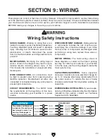
Page 82: ...cZ deZgVi dc 9djWaZ X ZX Vaa l gZh Y h XdccZXiZY dg XdccZXiZY Yjg c Vcn l g c iVh id ZchjgZ i i XdccZXi dch CIRCUIT REQUIREMENTS Ndj BJHI daadl i Z gZfj gZbZcih Vi i Z WZ cc c d i h bVc jVa l Zc Xdcc...

Page 83: ...ed 5 20 PLUG As Recommended 220V 110V G I ZgbVa 8 gXj i 7gZV Zg HiVgi 8VeVX idg B 9 K68 Gjc 8VeVX idg B 9 K68 gdjcY gdjcY Installation work and electrical wiring must be done by qualified electrician...

Page 84: ...urrent at the time of printing however always use the diagram on the inside of junction box cover when rewiring your motor gdjcY gdjcY HiVgi 8VeVX idg B 9 K68 Gjc 8VeVX idg B 9 K68 6 15 PLUG As Recomm...

Page 85: ...80 Model G0661 G0713 Mfg Since 1 10 Table Saw Body Breakdown SECTION 10 PARTS K K K K K K K K K K K K K K K K K E K K E BDIDG E K K E BDIDG...

Page 86: ...M CAP SCREW M8 1 25 X 20 76 P0661076 CABINET 32 PN03M HEX NUT M8 1 25 77 P0661077 REUSABLE BEADED CABLE TIE 33 P0661033 EXTENSION SPRING 78 P0661078 STRAIN RELIEF SB8R 3 34 PFB28M FLANGE BOLT M6 1 X 4...

Page 87: ...0661082 5 JUNCTION BOX 82 6 P0661082 6 MOTOR FAN COVER 82 7 P0661082 7 MOTOR FAN 82 8 P0661082 8 CAPACITOR COVER 82 9 P0661082 9 S CAP 200M 250V 1 1 2 X 2 3 4 82 10 P0661082 10 R CAP 30M 350V 1 1 2 X...

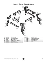
Page 88: ...ON REF PART DESCRIPTION 96 PW01M FLAT WASHER 8MM 101 P0661101 LOWER STAND BRACE 97 PN03M HEX NUT M8 1 25 102 P0661102 SIDE STAND BRACE 98 PCB11M CARRIAGE BOLT M8 1 25 X 12 103 P0661103 LEFT STAND LEG...

Page 89: ...AZ LABEL V2 01 10 2V2 8 P0661002V2 8 ROD V2 01 10 12 H8243 SWITCH ASSEMBLY 2V2 9 P0661002V2 9 LEFT BRACKET V2 01 10 12 1 PS18M PHLP HD SCR M4 7 X 25 2V2 10 P0661002V2 10 RIGHT BRACKET V2 01 10 12 2 PL...

Page 90: ...26 PFH49M FLAT HD SCR M3 5 X 6 1 7V2 P0661001 7V2 POINTER 2 PCS V2 12 09 7 P0661007 RAIL 1 9V2 PS37M PHLP HD SCR M6 1 X 6 7 1 P0661007 1 SPECIAL CAP SCREW M8 1 25 X 25 1 10 P0661001 10 FENCE 7 2 P0661...

Page 91: ...ew labels REF PART DESCRIPTION REF PART DESCRIPTION 2V2 28 P0661002V2 28 AMPUTATION HAZ LABEL V2 01 10 208 PLABEL 57 GLASSES RESPIRATOR LABEL 203 PLABEL 14 ELECTRICITY LABEL 209 PPAINT 11 PUTTY TOUCHU...

Page 92: ...Vgh TTTT NZVgh TTTT NZVgh 6 dl bVcn d ndjg bVX cZh dg iddah VgZ g ooan4 TTTT TTTT TTTT TTTT 7 9d ndj i c ndjg bVX cZ gZegZhZcih V ddY kVajZ4 TTTTTNZh TTTTTCd 8 LdjaY ndj gZXdbbZcY g ooan cYjhig Va id...

Page 93: ...I HI6EA DA9 6ADC 9DII 9 A C DA9 6ADC 9DII 9 A C 2 9 5342 0 8 7 EaVXZ HiVbe ZgZ CVbZTTTTTTTTTTTTTTTTTTTTTTTTTTTTTTT HigZZiTTTTTTTTTTTTTTTTTTTTTTTTTTTTTTT 8 inTTTTTTTTTTTTTTHiViZTTTTTTO eTTTTTT HZcY V g...

Page 94: ...h Vaa WZ ig ZY c i Z HiViZ d LVh c idc 8djcin d L ViXdb LZ h Vaa c cd ZkZci WZ a VWaZ dg YZVi c_jg Zh id eZghdch dg egdeZgin dg dg cX YZciVa Xdci c Zci heZX Va dg XdchZfjZci Va YVbV Zh Vg h c gdb i Z...

Page 95: ...Buy Direct and Save with Grizzly Trusted Proven and a Great Value Since 1983 ORDER 24 HOURS A DAY 1 800 523 4777 Visit Our Website Today For Current Specials...

Reviews: