background image

Model G0671/G0672/G0673 (Mfd. Since 6/17)

-23-

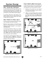
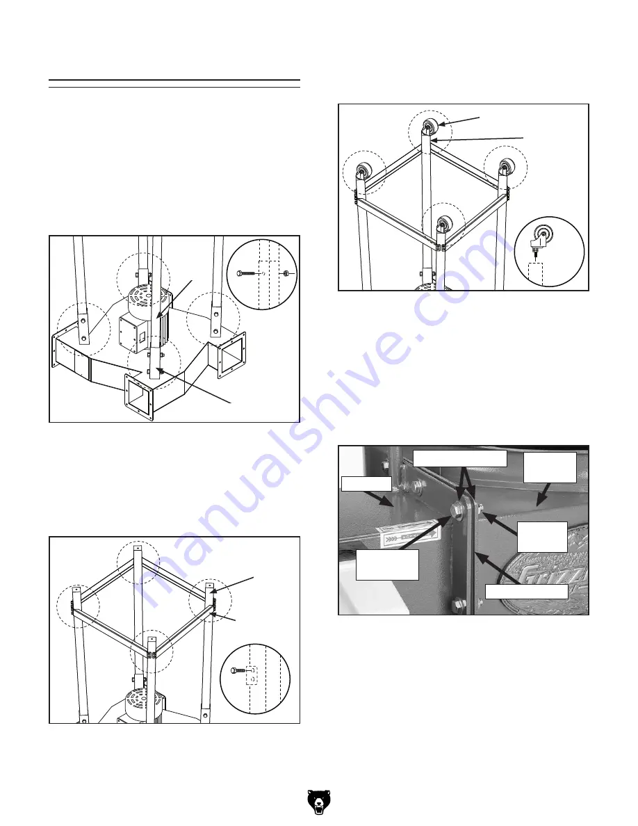
To assemble the dust collector:

1.  With  assistance,  place  the  impeller  housing 

on the floor so that the motor is pointing up.

2.  Insert the legs into the leg mounting brackets 

and secure them with the eight 

5

16

"-18 x 2 

1

2

hex bolts and 

5

16

"-18 hex nuts, as shown in 

Figure 8. Do not yet fully tighten the nuts.

Figure 8.

 Attaching legs to impeller housing 

(Model G0673 shown).

x8

Leg Mounting Bracket

Leg

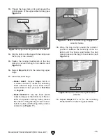
3.  Attach  the  four  leg  braces  to  the  legs  with 

the (16) 

5

16

"-18 x 

1

2

" hex bolts, as shown in 

Figure 9. Fully tighten the bolts and the hard-
ware from 

Step 2.

Figure 9. Attaching leg braces.

x16

Leg Brace

Leg

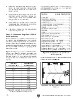
4.  Attach the four casters to the legs by thread-

ing  them  into  the  bottom  of  the  legs,  as 
shown in 

Figure 11.

5.  With  assistance,  turn  the  entire  assembly 

over so that the casters rest on the floor.

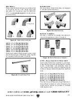
6.  Use  (8) 

5

16

"-18  x  1"  hex  bolts,  (16) 

5

16

"  flat 

washers,  and  (8) 

5

16

"-18  hex  nuts  to  attach 

each collector to the impeller housing with a 
rubber  gasket  between  the  components,  as 
shown in 

Figure 10.

Figure 10. Attaching casters.

x4

Caster

Leg

Figure 11. Collector mounted to impeller 

housing.

Rubber Gasket

Collector

5

16

"-18 x 1" 

Hex Bolt

5

16

"-18 

Hex Nut

5

16

" Flat Washers

Impeller 

housing

Assembly

Summary of Contents for G0671

Page 1: ...Single Phase G0672 5 HP 220V Single Phase G0673 10 HP 220 440V 3 Phase COPYRIGHT MAY 2008 BY GRIZZLY INDUSTRIAL INC REVISED NOVEMBER 2017 HE WARNING NO PORTION OF THIS MANUAL MAY BE REPRODUCED IN ANY...

Page 2: ...g grinding tool integrity and the usage of personal protective equipment The manufacturer will not be held liable for injury or property damage from negligence improper training machine modifications...

Page 3: ...ons 22 Assembly 23 Test Run 26 SECTION 4 DESIGNING THE SYSTEM 27 General 27 Duct Material 27 System Design 29 System Grounding 34 SECTION 5 OPERATIONS 35 Basic Controls 35 General 35 SECTION 6 ACCESSO...
Page 4: ...rsion We post current manuals and manual updates for free on our web site at www grizzly com Alternatively you can call our Technical Support for help Before calling make sure you write down the Manuf...

Page 5: ...nce 6 17 3 Identification Inlet ON OFF Power Switch Upper Bag Collector Collection Bag Caster Base Motor Hidden From View Upper Bag Hanger Assembly To reduce your risk of serious injury read this enti...

Page 6: ...Height 42 x 29 x 30 in Must Ship Upright Yes Electrical Power Requirement 220V Single Phase 60 Hz Prewired Voltage 220V Full Load Current Rating 26A Minimum Circuit Size 40A Connection Type Permanent...

Page 7: ...14 1 2 in Impeller Blade Thickness 1 4 in Construction Upper Bag Fabric Lower Bag Plastic Frame Steel Sheet Metal w Casters Impeller Steel Paint Type Finish Powder Coated Body Steel Sheet Metal Other...

Page 8: ...SULTS Max CFM Max SP HP Volts Inlet Impeller 3551 6 13 5 4 HP 220V 10 141 2 Inlet Dia inch 10 9 8 7 6 5 4 3 2 CFM 3551 6 3454 8 3282 6 2916 6 2475 4 2098 7 1452 9 979 4 484 3 Static Pressure Inch H2O...

Page 9: ...0 in Must Ship Upright Yes Electrical Power Requirement 220V Single Phase 60 Hz Prewired Voltage 220V Full Load Current Rating 34A Minimum Circuit Size 50A Connection Type Permanent Hardwire to Shutof...

Page 10: ...Impeller Blade Thickness 1 4 in Construction Upper Bag Fabric Lower Bag Plastic Frame Steel Sheet Metal w Casters Caster Rubber Impeller Steel Paint Type Finish Powder Coated Blower Housing Formed Ste...

Page 11: ...CTOR PERFORMANCE RESULTS Max CFM Max SP HP Volts Inlet Impeller 3960 6 14 6 5HP 220V 10 15 Inlet Dia inch 10 9 8 7 6 5 4 3 2 CFM 3960 6 3809 9 3336 4 2744 4 2206 3 1560 6 1140 8 861 0 656 5 Static Pre...

Page 12: ...pright Yes Electrical Power Requirement 220V or 440V 3 Phase 60 Hz Prewired Voltage 220V Full Load Current Rating 30A at 220V 15A at 440V Minimum Circuit Size 40A at 220V 20A at 440V Connection Type P...

Page 13: ...17 in Impeller Blade Thickness 1 4 in Construction Upper Bag Fabric Lower Bag Plastic Frame Steel Sheet Metal w Casters Caster Rubber Impeller Steel Paint Type Finish Powder Coated Blower Housing For...

Page 14: ...HP Volts Inlet Impeller 5359 7 17 9 10HP 220V 10 17 Inlet Dia inch 10 9 8 7 6 5 4 3 2 CFM 5359 7 5176 8 4229 7 3390 2 2604 5 1678 9 968 6 430 5 344 4 Static Pressure Inch H2O 10 08 10 64 12 96 14 72 1...

Page 15: ...kid proof DANGEROUS ENVIRONMENTS Do not use machinery in areas that are wet cluttered or have poor lighting Operating machinery in these areas greatly increases the risk of accidents and injury MENTA...

Page 16: ...with moving parts or flying debris Make sure they are properly installed undamaged and working correctly BEFORE operating machine FORCING MACHINERY Do not force machine It will do the job safer and b...

Page 17: ...fire extinguisher nearby STATIC ELECTRICITY To reduce risk of fire or explosions caused by sparks from static electricity ground all ducting using grounding wire DUST ALLERGIES Dust from certain wood...

Page 18: ...des all electrical equipment between the breaker box or fuse panel in the building and the machine The power sup ply circuit used for this machine must be sized to safely handle the full load current...

Page 19: ...t 40 Amps Connection Type A permanently connected hardwired power sup ply is typically installed with wires running through mounted and secured conduit A disconnecting means such as a locking switch s...

Page 20: ...del G0673 can be converted for 440V operation This conversion job consists of dis connecting the machine from the power source changing the connections on the magnetic switch and rewiring the motor fo...

Page 21: ...h the machine and have resolved any issues between Grizzly or the shipping agent You MUST have the original pack aging to file a freight claim It is also extremely helpful if you need to return your m...

Page 22: ...20 x 1 2 hangers 6 Flat Washers 5 16 collectors 32 Phillips Head Screw 10 24 X 3 8 inlet 1 Bag Clamps bags 4 Figure 3 G0671 G0672 Inventory 1 D C A B E Figure 4 G0671 G0672 Inventory 2 G H I J K L NO...

Page 23: ...1 2 hangers 12 Flat Washers 5 16 collectors 64 Phillips Head Screw 10 24 X 3 8 inlet 1 Figure 5 G0673 Inventory 1 A B C D E F H I J Figure 6 G0673 Inventory 2 K L M Figure 7 G0673 Inventory 3 The fol...

Page 24: ...ation Physical Environment The physical environment where the machine is operated is important for safe operation and lon gevity of machine components For best results operate this machine in a dry en...

Page 25: ...bolts as shown in Figure 9 Fully tighten the bolts and the hard ware from Step 2 Figure 9 Attaching leg braces x16 Leg Brace Leg 4 Attach the four casters to the legs by thread ing them into the botto...

Page 26: ...with one Model G0673 or two Model G0671 G0672 1 4 20 x 1 2 hex bolts see Figure 13 10 Align the hanger assembly so that the hook is directly over the center of the collector 11 Repeat Steps 8 10 for t...

Page 27: ...g lower collection bags on the lower rims of each collector Then proceed to Test Run on Page 26 Model G0672 73 Slip the lower plastic collection bag over the bottom lip of the col lector and position...

Page 28: ...ine should run smoothly with little or no vibration or rubbing noises Strange or unusual noises should be inves tigated and corrected before operating the machine further Always disconnect the machine...

Page 29: ...ur system design using this feature bags may fill at different rates requiring you to empty some bags more often than others Whatever system you choose always make sure there are no open flames includ...

Page 30: ...choice for flexible ducting is metal flex hose that is designed to be flexible and as smooth as possible to reduce static pressure loss Figure 20 Example of flexible metal duct There are also many kin...

Page 31: ...int a basic shop layout Don t worry non Grizzly brand machines can be substituted with Grizzly machines for layout pur poses Note After you re finished make sure to save your layout for later modifica...

Page 32: ...uld be placed near the dust collector If the machine has multiple dust ports the total CFM required is the sum of all ports Figure 25 Approximate required airflow for machines based on dust port size...

Page 33: ...t port Note Systems with powerful dust collectors work better if multiple blast gates are left open This also allows you to run two machines at once Experiment with different combinations of blast gat...

Page 34: ...ipe Main Lines at 3500 FPM Branch Lines at 4000 FPM Main Lines at 3500 FPM Branch Lines at 4000 FPM 2 0 091 0 122 0 35 0 453 2 5 0 08 0 107 0 306 0 397 3 0 071 0 094 0 271 0 352 4 0 057 0 075 0 215 0...

Page 35: ...cessary to make your system a reality If the CFM for your static pressure loss is below the requirement of the machine then that line will not effectively collect the dust You must then modify some of...

Page 36: ...the dust collector We recommend using flexible hose flex hose to con nect the woodworking machine to the dust collec tion system However plastic flex hose and plastic duct are insulators and dust par...

Page 37: ...A dust collector should NEVER be used as a shop vacuum For safest use wear a respirator and use an air cleaner in addition to the dust collector ON OFF To reduce your risk of serious injury read this...

Page 38: ...mage To reduce this risk only install accessories recommended for this machine by Grizzly NOTICE Refer to our website or latest catalog for additional recommended accessories G0673036 Mag Switch 3 Pha...

Page 39: ...esigned to minimize airflow resistance Figure 43 Metal Branches Reducers Adapters We carry a multitude of reducers and elbows to cover most applications from 4 through 9 Figure 44 Metal Reducers Adapt...

Page 40: ...adjusts from 23 to 43 high Every shop needs one of these Figure 48 T10117 Big Mouth Dust Hood T10115 Benchtop Downdraft Table G3119 4 x 21 2 Adapter Want to stop making such a mess when sanding This...

Page 41: ...em Bag Cleaning Empty the lower collection bags on a regular basis to maintain dust collection efficiency Always wear the appropriate respirator or dust mask and safety glasses when emptying the col l...

Page 42: ...otor connection is wired incorrectly 2 Plug receptacle is at fault 3 Motor bearings are at fault 4 Motor has overheated 5 Contactor not getting energized or has poor contacts 6 Motor is at fault 7 Cen...

Page 43: ...enough open branch lines at one time thereby causing a velocity drop in the main line 7 The ducting and ports are incorrectly sized 8 The machine dust collection design is inadequate 9 The dust colle...

Page 44: ...current at the time of printing but may not match your machine If you find this to be the case use the wiring diagram inside the motor junction box CAPACITORS INVERTERS Some capacitors and power inver...

Page 45: ...T1 2 T3 6 8 3 4 T2 4 L1 1 L3 5 7 L2 3 5 6 95 22 28 34 OFF SDE Gn Gn Bk Gn Gn Gn Locking Shut Off Switch As Recommended GND Gn Bk Bk Bk Bk Bk Bk Bk Wt Bk Bk Wt Wt Hot Ground Start Capacitor 600MFD 250V...

Page 46: ...Bk Wt Wt Wt Wt AMP Set to 37 MA 30 Locking Shut Off Switch As Recommended MOTOR at 220V SINGLE PHASE Gn Ground Gn Bk Bk Wt Hot Ground Run Capacitor 50MFD 250VAC Rd Rd Wt Start Capacitor 800MFD 250VAC...

Page 47: ...ot Hot Gn Wt Bk Rd MOTOR at 220V 3 PHASE MOTOR at 440V 3 PHASE A B AMP RESET 96 98 1 2 T1 2 T3 6 14 3 4 T2 4 L1 1 L3 5 13 L2 3 5 6 95 22 28 34 OFF Ground Rd Bk Gn 3 2 1 5 4 6 7 9 8 If motor rotates in...

Page 48: ...46 Model G0671 G0672 G0673 Mfd Since 6 17 READ ELECTRICAL SAFETY ON PAGE 42 Figure 55 G0673 220V motor Figure 54 G0673 220V switch G0673 Electrical Components...

Page 49: ...15 18 28 29 30 16 20V2 18 30 29 38V2 19 21 26 38V2 5 1 3 41 2 33 31 32 36 35 34 4 40 28 17 17 15 12 27 19 19 19 25 7 8 22 24 23 22 21 27 26 37 13 39 1 2 1 1 1 3 1 4 1 7 1 6 1 5 1 8 40 20V2 42 33 2 33...

Page 50: ...MAGNETIC SWITCH 6 P0671006 HEX BOLT 5 16 18 X 3 4 33 1 P0671033 1 MAG SWITCH BACK COVER 7 P0671007 INLET COVER 33 2 P0671033 2 CONTACTOR SDE MP 15 220V 8 P0671008 IMPELLER 14 1 2 33 2A P0671033 2A AUX...

Page 51: ...6 10 11 9 17 17 15 18 28 29 30 16 20 18 30 29 38 19 21 26 38 19 5 1 3 2 33V3 31 32 36 35 34 4 28 17 17 15 12 27 19 19 25 7 8 22 24 23 22 21 27 26 37 13 39 1 2 1 1 1 4 1 7 1 6 1 5 1 8 40 40 41 42 33 2V...

Page 52: ...X BOLT 5 16 18 X 3 4 33 1 P0672033 1 MAG SWITCH BACK COVER 7 P0672007 INLET COVER 33 2V2 P0672033 2V2 CONTACTOR SDE MA 30 220V V2 06 17 8 P0672008 IMPELLER 15 33 3V2 P0672033 3V2 OL RELAY SDE RA 30 28...

Page 53: ...5 6 7 8 9 10 13 14 15 16 17 18 19 20 19 21 22 24 23 25 26 35 28 27 17 20 18 18 18 19 19 19 19 16 16 16 15 15 15 20 20 35 24 24 24 26 26 26 25 17 21 21 21 30 31 32 33 29 34 1 2 1 1 1 3 30 3 30 2 30 4 3...

Page 54: ...17 31 P0673031 STRAIN RELIEF 10 P0673010 HEX BOLT 3 8 16 X 1 1 2 32 P0673032 MOTOR CORD 10AWG X 4C 11 P0673011 FLAT WASHER 6MM 33 P0673033 POWER CORD 10AWG X 4C 12 P0673012 CAP SCREW M6 1 X 20 34 P06...

Page 55: ...REPLACE that label before using the machine again Contact Grizzly at 800 523 4777 or www grizzly com to order new labels REF PART DESCRIPTION 50 P0671050 HANDS INLET WARNING G0671 G0672 51 P0671051 MA...

Page 56: ......

Page 57: ...metalworker ____ 0 2 Years ____ 2 8 Years ____ 8 20 Years ____20 Years 6 How many of your machines or tools are Grizzly ____ 0 2 ____ 3 5 ____ 6 9 ____10 7 Do you think your machine represents a good...

Page 58: ...LINE FOLD ALONG DOTTED LINE GRIZZLY INDUSTRIAL INC P O BOX 2069 BELLINGHAM WA 98227 2069 Place Stamp Here Name_______________________________ Street_______________________________ City______________S...

Page 59: ...tried in the State of Washington County of Whatcom We shall in no event be liable for death injuries to persons or property or for incidental contingent special or consequential damages arising from...

Page 60: ......

Reviews: