-24-
Model G0699 (Mfd. Since 5/15)
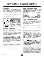
11. Insert the (3) M12-1.75 x 60 T-bolts into the
sliding table T-slot, as shown in
Figure 20,
and space them apart the same distance as
the mounting holes in the frame top.
Figure 20. T-bolts inserted into the sliding table
T-slot.
Mounting
Hole
T-Bolt
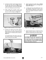
10. Attach the end handle to sliding table with
the cap screws removed in
Step 9. Slide the
sliding table base out of the way to install the
two larger cap screws shown in
Figure 19.
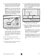
9. Remove the four cap screws threaded into
the end of the sliding table assembly, the cap
screw securing the lock handle, and the two
cap screws pre-installed in the end handle
(see
Figure 18).
Figure 18. Cap screws to remove for end handle
installation.
Remove These
Cap Screws
End
Handle
Figure 19. End handle installed.
Cap Screws
Base
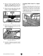
Figure 17. Sliding table saw upside down.
8. Turn the sliding table assembly upside down,
as shown in
Figure 17.
Summary of Contents for G0699
Page 21: ...Model G0699 Mfd Since 5 15 19 5mm Hardware Recognition Chart...
Page 108: ......


