Model G0699 (Mfd. Since 5/15)
-27-
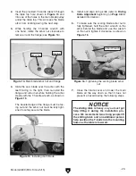
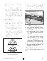
25. With the help of another person to hold the
forward extension wing, attach it to the cast
iron table with (2) M10-1.5 x 25 cap screws,
10mm lock washers, and 10mm flat washers,
as shown in
Figure 27.
Hand tighten the cap screws for now—they
will be fully tightened in a later step.
Figure 27. Forward extension wing attached (as
viewed under the wing).
Cap Screws
& Set Screws
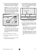
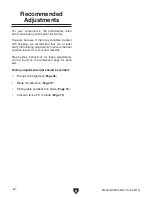
26. With the help of two other people to hold
the rear extension wing, attach it to the cast
iron table with (3) M10-1.5 x 25 cap screws,
10mm lock washers, and 10mm flat washers,
as shown in
Figure 28.
Hand tighten the cap screws for now—they
will be fully tightened in a later step.
27. Thread (5) M10-1.5 x 20 set screws into
the threaded holes under each of the
extension wing cap screws on both wings
(see
Figures 27–28).
Make sure the set screws do not stick out
from the wing mating surface, which would
interfere with the leveling process in the next
step.
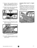
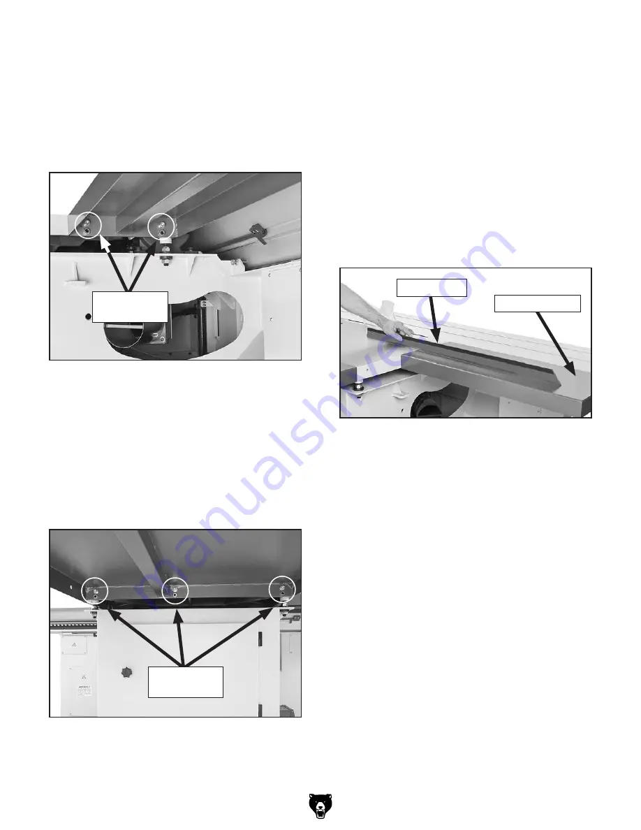
28. Place the straightedge across the cast iron
table and an extension wing, then adjust the
set screws in or out to make the top surface
of the wings even with that of the cast iron
table (see
Figure 29).
Figure 28. Rear extension wing attached.
Cap Screws
& Set Screws
29. When the top surfaces are even, thread (5)
M10-1.5 hex nuts onto the set screws without
changing their settings. Fully tighten the hex
nuts to secure the set screws in place.
30. Fully tighten the extension wing cap screws,
then re-check to make sure the top surfaces
remain even.
— If the top surfaces did not remain even after
tightening the cap screws, loosen them,
then repeat
Steps 28–30 until they remain
even.
Figure 29. Using a straightedge to make sure
the table/wing top surfaces are even.
Extension Wing
Straightedge
Summary of Contents for G0699
Page 21: ...Model G0699 Mfd Since 5 15 19 5mm Hardware Recognition Chart...
Page 108: ......


