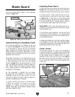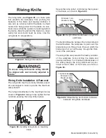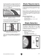
Model G0699 (Mfd. Since 5/15)
-35-
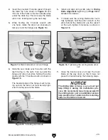
61. Tighten jam nut against bracket (see Figure
53) to secure arm-leveling bolt.
62. Secure arm-support base with (2) M20-2.5
hex nuts and (2) 20mm fender washers (see
Figure 53).
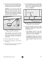
63. Install arm-support pedestal on arm-support
base, using (4) M8-1.25 x 25 cap screws, (4)
8mm lock washers, and (4) 8mm flat washers
(see
Figure 54).
Figure 54. Installing arm-support pedestal.
Arm-Support
Pedestal
x 4
Figure 53. Securing arm-support base.
Bracket
Arm-Leveling
Bolt
M20-2.5 Hex Nut
w/Fender Washer
(1 of 2)
Jam Nut
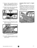
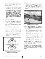
64. Insert upper support arm into top of arm-
support pedestal, as shown in
Figure 55.
65. Install (1) M10-1.5 x 30 hex bolt into location
shown in
Figure 55. Do not tighten yet.
Upper
Support Arm
x 1
Figure 55. Installing upper support-arm.
Top of Arm
Support Pedestal
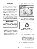
66. Install 4" dust port adapter on upper support
arm, using (2) M6-1 x 12 button head cap
screws, (2) 6mm lock washers, and (2) 6mm
flat washers (see
Figure 56).
Base
Figure 56. Installing 4" dust port adapter.
x 2
4" Dust Port
Adapter
Summary of Contents for G0699
Page 21: ...Model G0699 Mfd Since 5 15 19 5mm Hardware Recognition Chart...
Page 108: ......


