-36-
Model G0699 (Mfd. Since 5/15)
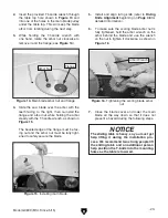
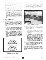
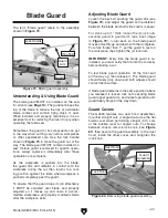
69. Slide upper support arm until at least one
blade guard roller is centered over blade (see
Figure 59), then tighten hex bolt from Step
65 on Page 35 to secure upper support arm.
Figure 59. Blade guard rollers centered over
blade.
Blade Guard
Roller (1 of 2)
Blade
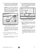
70. Ensure front and rear blade guard rollers are
parallel with blade (see
Figure 59).
— If rollers are parallel with blade, proceed to
Step 62.
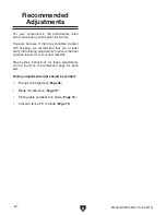
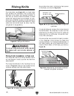
— If rollers are not parallel with blade, loosen
cap screws shown in
Figure 60, adjust
arm-support pedestal until rollers are par-
allel with blade, then re-tighten cap screws
to secure. Check to make sure both blade
rollers are centered over blade, and if
necessary, loosen hex bolt from
Step 65
on
Page 35, slide upper support arm until
rollers are centered over blade, then re-
tighten hex bolt to secure.
Figure 60. Adjusting alignment of arm-support
pedestal.
Cap Screws
that Secure
Arm Support
Pedestal
Arm Support
Pedestal
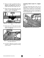
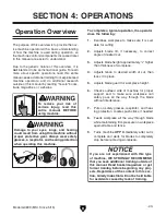
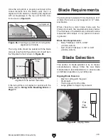
68. Attach connection plate assembly to end of
upper support arm, using (3) M6-1 x 20 cap
screws, (3) 6mm lock washers, and (3) 6mm
flat washers (see
Figure 58).
Figure 58. Connection plate assembly attached
to upper support arm.
Connection Plate
Assembly
x 3
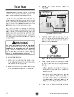
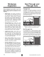
Figure 57. Installing blade guard connection
plate assembly onto blade guard assembly.
67. Attach connection plate assembly with return
spring to blade guard using (2) M6-1 lock
nuts (see
Figure 57).
Blade
Guard
Assembly
Return Spring
Connection Plate
Assembly
Summary of Contents for G0699
Page 21: ...Model G0699 Mfd Since 5 15 19 5mm Hardware Recognition Chart...
Page 108: ......


