background image

WARRANTY AND RETURNS

Grizzly Industrial, Inc. warrants every product it sells for a period of 

1 year to the original purchaser from 

the date of purchase. This warranty does not apply to defects due directly or indirectly to misuse, abuse, 
negligence, accidents, repairs or alterations or lack of maintenance. This is Grizzly’s sole written warranty 
and any and all warranties that may be implied by law, including any merchantability or fitness, for any par-
ticular purpose, are hereby limited to the duration of this written warranty. We do not warrant or represent 
that the merchandise complies with the provisions of any law or acts unless the manufacturer so warrants. 
In no event shall Grizzly’s liability under this warranty exceed the purchase price paid for the product and 
any legal actions brought against Grizzly shall be tried in the State of Washington, County of Whatcom.

We shall in no event be liable for death, injuries to persons or property or for incidental, contingent, special, 
or consequential damages arising from the use of our products.

To take advantage of this warranty, contact us by mail or phone and give us all the details. We will then 
issue you a “Return Number,’’ which must be clearly posted on the outside as well as the inside of the 
carton.  We  will  not  accept  any  item  back  without  this  number.  Proof  of  purchase  must  accompany  the 
merchandise. 

The manufacturers reserve the right to change specifications at any time because they constantly strive to 
achieve better quality equipment. We make every effort to ensure that our products meet high quality and 
durability standards and we hope you never need to use this warranty.

Please feel free to write or call us if you have any questions about the machine or the manual. 

Thank you again for your business and continued support. We hope to serve you again soon.

WARRANTY AND RETURNS

Summary of Contents for G0700

Page 1: ...015 MN WARNING NO PORTION OF THIS MANUAL MAY BE REPRODUCED IN ANY SHAPE OR FORM WITHOUT THE WRITTEN APPROVAL OF GRIZZLY INDUSTRIAL INC TR12474 PRINTED IN TAIWAN MODEL G0700 10 SLIDING TABLE SAW OWNER...

Page 2: ...g grinding tool integrity and the usage of personal protective equipment The manufacturer will not be held liable for injury or property damage from negligence improper training machine modifications...

Page 3: ...lection 32 Changing Main Blade 34 Changing Adjusting Scoring Blade 35 Rip Cutting 36 Crosscutting 38 Miter Cutting 39 Dado Cutting 40 Rabbet Cutting 42 Resawing 44 SECTION 5 SHOP MADE SAFETY ACCESSORI...

Page 4: ...Technical Support 1203 Lycoming Mall Circle Muncy PA 17756 Phone 570 546 9663 Email techsupport grizzly com We want your feedback on this manual What did you like about it Where could it be improved P...

Page 5: ...Clamp Sliding Table Lock Rip Fence Fine Adjust Knob Rip Fence Lock Lever Upper Blade Guard Riving Knife Junction Box Lower Blade Guard Main Blade Scoring Blade Main Blade Arbor Lock Access Hole Scorin...

Page 6: ...Shipping Dimensions Type Wood Crate Content Machine Weight 584 lbs Length x Width x Height 42 x 46 x 41 in Electrical Power Requirement 230V Single Phase 60 Hz Full Load Current Rating 19A Minimum Ci...

Page 7: ...n Table Size With Ext Wings Width 39 3 4 in Sliding Table Length 39 3 8 in Sliding Table Width 12 1 4 in Fence Information Crosscut Fence Type Single Lever Locking Extruded Aluminum Construction Mater...

Page 8: ...g TABle SAW Customer Service 570 546 9663 To Order Call 800 523 4777 Fax 800 438 5901 SlIdINg TABle SAW CAPACITIeS Ripping Width Miter Cut 45 w Miter Fence Maximum Cutting Length w o Scoring Blade Mit...

Page 9: ...rkshop kid proof DANGEROUS ENVIRONMENTS Do not use machinery in areas that are wet cluttered or have poor lighting Operating machinery in these areas greatly increases the risk of accidents and injury...

Page 10: ...moving parts or flying debris Make sure they are properly installed undamaged and working correctly BEFORE operating machine FORCING MACHINERY Do not force machine It will do the job safer and better...

Page 11: ...fence during cutting operation Never start saw with workpiece touching blade Allow blade to reach full speed before cutting Only feed workpiece against direc tion of main blade rotation Always use so...

Page 12: ...sure rip fence is adjusted parallel with the blade otherwise the chances of kickback are extreme Take the time to check and adjust the rip fence before cutting Preventing Kickback Even if you know how...

Page 13: ...nt in which the spinning blade ejects the workpiece toward the front of the saw at a high rate of speed Non Through Cut A cut in which the blade does not cut through the top of the workpiece Refer to...

Page 14: ...e may result especially if connected to an undersized circuit To reduce the risk of these hazards avoid over loading the machine during operation and make sure it is connected to a power supply circui...

Page 15: ...used with this machine must be in good condition and contain a ground wire and matching plug receptacle Additionally it must meet the following size requirements Minimum Gauge Size 10a AWG Maximum Len...

Page 16: ...or possible inspection by the carrier or its agent Otherwise filing a freight claim can be difficult When you are completely satisfied with the condi tion of your shipment you should inventory the con...

Page 17: ...Model G0700 Mfd Since 5 14 15 Hardware Recognition Chart...

Page 18: ...of expediency replacements can be obtained at your local hardware store Item Figure 2 Qty A Table Saw 1 A Figure 2 Table saw base unit Item Figure 3 Qty B Extension Table 1 C Hose Support 1 D Dust Ho...

Page 19: ...Screw M10 1 5 x 25 Hose Support 1 Flat Washers 10mm Hose Support 2 Lock Washer 10mm Hose Support 1 Hex Nut M10 1 5 Hose Support 1 Item Figure 5 Qty K Push Handle Assembly w Lock 1 L Miter Gauge Assem...

Page 20: ...c paint scraper optional Basic steps for removing rust preventative 1 Put on safety glasses 2 Coat the rust preventative with a liberal amount of cleaner degreaser then let it soak for 5 10 minutes 3...

Page 21: ...ysical Environment The physical environment where the machine is operated is important for safe operation and lon gevity of machine components For best results operate this machine in a dry environmen...

Page 22: ...ting straps sliding table removed for clarity This machine and its components are heavy Serious injury may occur if safe moving methods are not followed Get help when lifting or moving the machine and...

Page 23: ...of the extension table to be even with the cast iron table and snug the cap screws down enough to hold the table in place 4 Using a straightedge as a guide see Figure 11 adjust the set screws to align...

Page 24: ...the rail still needs to be adjusted Figure 14 Round rail installed 9 Slide the rip fence base onto the round rail Thread the handles and knob into the rip fence base where shown in Figure 15 10 Slide...

Page 25: ...cover and blade arbors 16 Insert the arbor lock tool into the hole shown in Figure 21 rotate the arbor until the arbor lock tool seats then install the main blade per the instructions on Page 35 as a...

Page 26: ...the table Note The rip fence body will scratch the table surface if the ride height is not adjusted correctly Only the roller should touch the table surface If the rip fence body does not rest on the...

Page 27: ...sher 10mm Flat Washer 10mm Large Extension Table Cap Screw M10 1 5 x 25 Hex Nut M10 1 5 Figure 26 Miter gauge installed Miter Gauge 27 Install miter gauge as shown in Figure 26 Figure 25 Blade guard i...

Page 28: ...chine 3 number of branches or wyes and 4 amount of other open lines throughout the system Explaining how to calculate these variables is beyond the scope of this manual Consult an expert or pur chase...

Page 29: ...advice before proceeding any further with the test run or machine operations 5 If you successfully completed Steps 1 4 above congratulations The table saw is now ready for cutting operations Test Run...

Page 30: ...th of cut then locks it in place 5 Checks the outfeed side of the machine for proper support and to make sure the workpiece can safely pass all the way through the blade without interference 6 Puts on...

Page 31: ...ing Material Type This machine is intended for cutting natural and man made wood prod ucts laminate covered wood products and some plastics Cutting drywall or cementitious backer board creates extreme...

Page 32: ...blade if a kick back occurs and the operator is reaching behind the blade Reaching behind the blade is a major safety risk and should not be done The blade guard MUST be installed on the saw for all n...

Page 33: ...en it is functioning cor rectly and is ready for operation If the blade guard remains in the position where you released it or it does not drop down against the surface of the table then the mounting...

Page 34: ...on measur ing device Blade Size Requirements Body Thickness 0 079 0 090 2 0mm 2 3mm Kerf Tooth Thickness 0 122 0 129 3 1mm 3 3mm Blade Requirements Figure 37 Ripping blade Blade Selection This section...

Page 35: ...teeth Alternate top bevel and flat or alternate top bevel and raker tooth profile Teeth are arranged in groups Gullets are small and shallow similar to a cross cut blade then large and deep similar to...

Page 36: ...ock tool seats Figure 43 Replacing the main blade Arbor Lock Tool This saw performs best with high quality sharp blades Whenever the blades become dull replace or have them sharpened To change the mai...

Page 37: ...th Also check on the other side of the blades to verify that the kerf thickness matches and the scor ing blade is aligned with the main blade 5 Tighten the controls lock 6 Move the blade cover back in...

Page 38: ...er fence on the sliding table as shown in Figure 49 2 Adjust the fence angle to 0 using the angle scale on the miter gauge If the cut requires extreme precision adjust the miter fence as described in...

Page 39: ...t lining up the edge of the rip fence where necessary on the scale see Figure 52 then locking the fence in place 4 Load the workpiece onto the table saw The set up should look similar to Figure 48 5 A...

Page 40: ...th miter fence in the rear position To perform a crosscutting operation 1 Install the miter fence in either of the two positions shown in Figures 53 54 2 Adjust the fence angle to 0 using the angle sc...

Page 41: ...ccording to the length of the workpiece you want to cut off to the left of the blade 4 Load the workpiece onto the table saw similar to Figure 58 and perform the cutting operation in the same manner a...

Page 42: ...desired width of cut according to the dado blade manufacturer s instructions 6 Install the dado blade on the arbor shaft as shown in Figure 62 This saw can only accept a dado blade with 5 8 arbor hole...

Page 43: ...greater amount of force against the workpiece when cutting This addition al force increases the risk of kickback requiring the operator to take additional steps when cutting to keep their injury risk...

Page 44: ...res a sacrificial fence Figure 67 Make the sacrificial fence the same length as the fence and 3 4 thick Attach it to the fence with screws or clamps making sure they are all secure and tight Raise the...

Page 45: ...saw to the power source and turn the saw ON When the blade has reached full speed perform a test cut with a scrap piece of wood If the cut is satisfactory repeat the cut with the final workpiece 3 Adj...

Page 46: ...e when resawing to provide tall support for the workpiece to minimize the probability of it binding against the blade and causing kickback Tools Needed Qty Table Saw 1 Jointer and Planer Recommended C...

Page 47: ...ks paddles and featherboards to keep your hands at a safe distance from the blade throughout the entire cut Always replace guard after completing the cut Fence Resaw Barrier 1 8 Connection Workpiece F...

Page 48: ...roximately 3 4 thick to size The length and width of the board can vary according to your design Most featherboards are 10 28 long and 3 6 wide Make sure the wood grain runs paral lel with the length...

Page 49: ...the coun tersunk hole in the center then use a jig saw with a narrow blade to cut it out 8 Assemble the miter bar and featherboard with a 1 4 20 x flat head screw flat washer and a wing nut or a star...

Page 50: ...he workpiece Mounting Featherboards w Clamps 4 Secure the featherboard to the table with a clamp 5 Check the featherboard by pushing it with your thumb to ensure it is secure If the featherboard moves...

Page 51: ...ck Push Stick Prohibition Zone Store Push Stick Here for Easy Access Supporting A second push stick can be used to keep the workpiece firmly against the fence while cutting When using a push stick in...

Page 52: ...ing a Push Block A push block can be used in place of or in addi tion to a push stick for feeding workpieces into the blade Due to their design push blocks allow the operator to apply firm downward pr...

Page 53: ...e insert additional modifications will need to be made in order to install the scoring blade and riving knife If you must use this saw to cut the dimen sions of the zero clearance insert you will fabr...

Page 54: ...rners or trim the ends as neces sary to get a precise fit 12 Mount the new table insert into the table and check to make sure that it is flush with the top of the table If necessary remove the insert...

Page 55: ...dwood 3 wide and as long as your table saw fence see Figure 91 Narrow Rip Auxiliary Fence Push Block 55 8 15 51 4 121 2 21 2 3 8 Lip Handle 3 8 5 8 21 2 Figure 93 Push block dimensions and constructio...

Page 56: ...te stop before removing the cut off piece Failure to follow this warn ing could result in serious personal injury Auxilliary Fence Blade Workpiece Push Stick for Side Support Blade Path Push Block Fig...

Page 57: ...commended accessories H6290 Scissor Lift Table 330 lb Capacity This rugged and affordable lifting table allows you to lift stacks of sheet goods right up to the saw table with just the power of your l...

Page 58: ...lade 100T These blades are designed especially for sliding table saws and manufactured for heavy duty use Figure 100 14 carbide tipped saw blade H8029 5 Piece Safety Kit This kit has four essential ji...

Page 59: ...maintenance necessary for any machine will always depend on the operating con ditions and environment The schedule below is a basic guideline for keeping your machine in prop er operating condition A...

Page 60: ...45 and reach inside the cabinet and smear a dab of grease into the back of the trunnion grooves on both sides Tilt the blade back and forth to distrib ute the grease evenly Figure 104 Sliding table w...

Page 61: ...onnections 4 Wait for it to cool down then it will reset auto matically If necessary disconnect power and reset manually by pushing reset button inside switch 5 Ensure circuit size is suitable for thi...

Page 62: ...ng table parallel with the blade Page 64 2 Adjust the riving knife to align it with the main blade 3 Replace the blade Workpiece has chip out on the bottom edge 1 Scoring blade height is incorrect 2 S...

Page 63: ...ght enough that it only deflects approximately 1 4 when pushed in the center with your thumb or index finger 8 Replace the motor cabinet door 5 Put the new scoring belt on the pulleys as shown in Figu...

Page 64: ...ill go 3 Use a machinist s square to check if the blade is square to the table If the blade is not square to the table loosen the two set screws that secure the 0 tilt stop nut shown in Figure 109 Fig...

Page 65: ...parallelism need to be made If the difference is greater than 0 004 then the sliding table parallelism must be adjusted Proceed to Step 7 7 Loosen the sliding table mounting nuts see Figure 112 at bot...

Page 66: ...n making additional adjustments and repeating the process until the sliding table moves as desired Ideally the table will move easily but without any slop The accuracy of the miter fence angle is depe...

Page 67: ...djust the each pair of set screws that controls the direction required to move the mounting block so the riving knife can be aligned with the blade Make sure to move both set screws in even increments...

Page 68: ...ration Double check all wires dis connected or connected during any wiring task to ensure tight connections CIRCUIT REQUIREMENTS You MUST follow the requirements at the beginning of this manual when c...

Page 69: ...itor 30MFD 500VAC EMERGENCY STOP SWITCH MAGNETIC SWITCH ASSEMBLY MOTOR 5HP 230V SINGLE PHASE L6 30 PLUG Ground Hot Hot 230 VAC G X Y POWER CONNECTION BOX BLADE GUARD LIMIT SWITCH Ground Ground Ground...

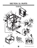
Page 70: ...1 2 4 3 6 6 7 7 8 9 9 10 11 11 12 12 12 14 15 16 17 18 19 19 20 20 20 23 24 25 25 25 27 29 55 56 57 58 32 33 36 37 38 41 42 43 46 48 49 50 51 52 53 59 60 61 62 28V2 54V2 4 54V2 1 54V2 2 54V2 3 54V2 40...

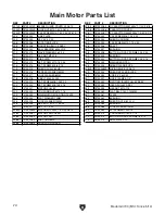
Page 71: ...700015 DUST PORT 54V2 P0700054V2 MAG SWITCH ASSY V2 06 14 16 P0700016 LOCK WASHER 6MM 54V2 1 P0700054V2 1 SWITCH BOX NHD 17 P0700017 PHLP HD SCR M6 1 X 16 54V2 2 P0700054V2 2 CONTACTOR NHD C 18D 230V...

Page 72: ...700103 HANDWHEEL ASSY 120 P0700120 CAP SCREW M8 1 25 X 50 104 P0700104 KEY 5 X 5 X 20 121 P0700121 LOCK WASHER 8MM 105 P0700105 TILT ADJ SHAFT ASSY 126 P0700126 BUSHING 111 P0700111 ELEVATION LEADSCRE...

Page 73: ...5 216 217 216 217 218 222 219 219 220 221 223 224 225 226 227 228V2 229 234 235 235 236 237 238 239 242 243 244 249 250 251 252 253 255 260 261 262 263 264 268 269 270 272 275 216 216 217 217 217 217...

Page 74: ...X 10 244 P0700244 ARBOR FLANGE CSA 215 P0700215 ARBOR PULLY 60HZ 248V2 P0700248V2 RIVING KNIFE V2 06 14 216 P0700216 FENDER WASHER 8MM 249 P0700249 ARBOR SPACER BLOCK 217 P0700217 LOCK WASHER 8MM 250...

Page 75: ...ST SHAFT 312 P0700312 FLAT WASHER 8MM 362 P0700362 CAP SCREW M8 1 25 X 100 313 P0700313 BLADE GUARD PLATE 363 P0700363 PLATE 314 P0700314 HINGE 364 P0700364 LOCK WASHER 8MM 315 P0700315 PHLP HD SCR M5...

Page 76: ...odel G0700 Mfd Since 5 14 401 402 403 404 405 406 407 408 409 409 409 409 409 410 411 412 413 414 461 451 452 453 454 455 457 458 459 460 461 462 465 463 464 464 465 460 466 466 467 467 468 468 469 Ta...

Page 77: ...HEX BOLT M6 1 X 25 407 P0700407 PUSH PULL HANDLE ASSY 460 P0700460 LOCK WASHER 6MM 408 P0700408 SLIDING TABLE BASE END PLATE 461 P0700461 HEX NUT M6 1 409 P0700409 BUTTON HD CAP SCR M6 1 X 12 462 P07...

Page 78: ...2 1 505V2 2 505V2 505V2 3 505V2 4 505V2 6 505V2 7 505V2 8 505V2 9 505V2 10 505V2 11 505V2 12 505V2 13 505V2 14 505V2 15 505V2 16 505V2 17 505V2 18 505V2 19 505V2 20 505V2 20 505V2 21 505V2 22 505V2 24...

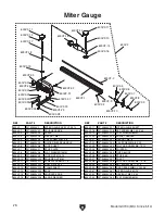
Page 79: ...M10 1 5 X 55 505V2 6 P0700505V2 6 FENCE RAIL BRACKET 505V2 31 P0700505V2 31 SHAFT 505V2 7 P0700505V2 7 LOCK NUT M10 1 5 505V2 32 P0700505V2 32 ROLLER 505V2 8 P0700505V2 8 LOCK DOWN HANDLE 505V2 33 P07...

Page 80: ...21 P0700600V2 21 HEX NUT M5 8 600V2 5 P0700600V2 5 QUICK RELEASE HANDLE 600V2 22 P0700600V2 22 CAP SCREW M5 8 X 25 600V2 6 P0700600V2 6 LOCK SHAFT 600V2 23 P0700600V2 23 PHLP HD SCREW M4 7 X 12 600V2...

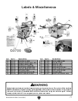
Page 81: ...bels REF PART DESCRIPTION REF PART DESCRIPTION 700 P0700700 READ MANUAL LABEL 709 P0700709 MODEL NUMBER LABEL 701 P0700701 TABLE SAW BLADE GUARD LABEL 710 P0700710 MACHINE ID LABEL 702 P0700702 KICKBA...

Page 82: ...metalworker ____ 0 2 Years ____ 2 8 Years ____ 8 20 Years ____20 Years 6 How many of your machines or tools are Grizzly ____ 0 2 ____ 3 5 ____ 6 9 ____10 7 Do you think your machine represents a good...

Page 83: ...LINE FOLD ALONG DOTTED LINE GRIZZLY INDUSTRIAL INC P O BOX 2069 BELLINGHAM WA 98227 2069 Place Stamp Here Name_______________________________ Street_______________________________ City______________S...

Page 84: ...tried in the State of Washington County of Whatcom We shall in no event be liable for death injuries to persons or property or for incidental contingent special or consequential damages arising from...

Page 85: ......

Reviews: