background image

Model G0701 (Mfd. Since 9/17)

-81-

BUY PARTS ONLINE AT GRIZZLY.COM!

Scan QR code to visit our Parts Store.

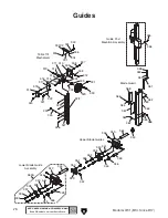
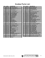
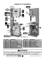
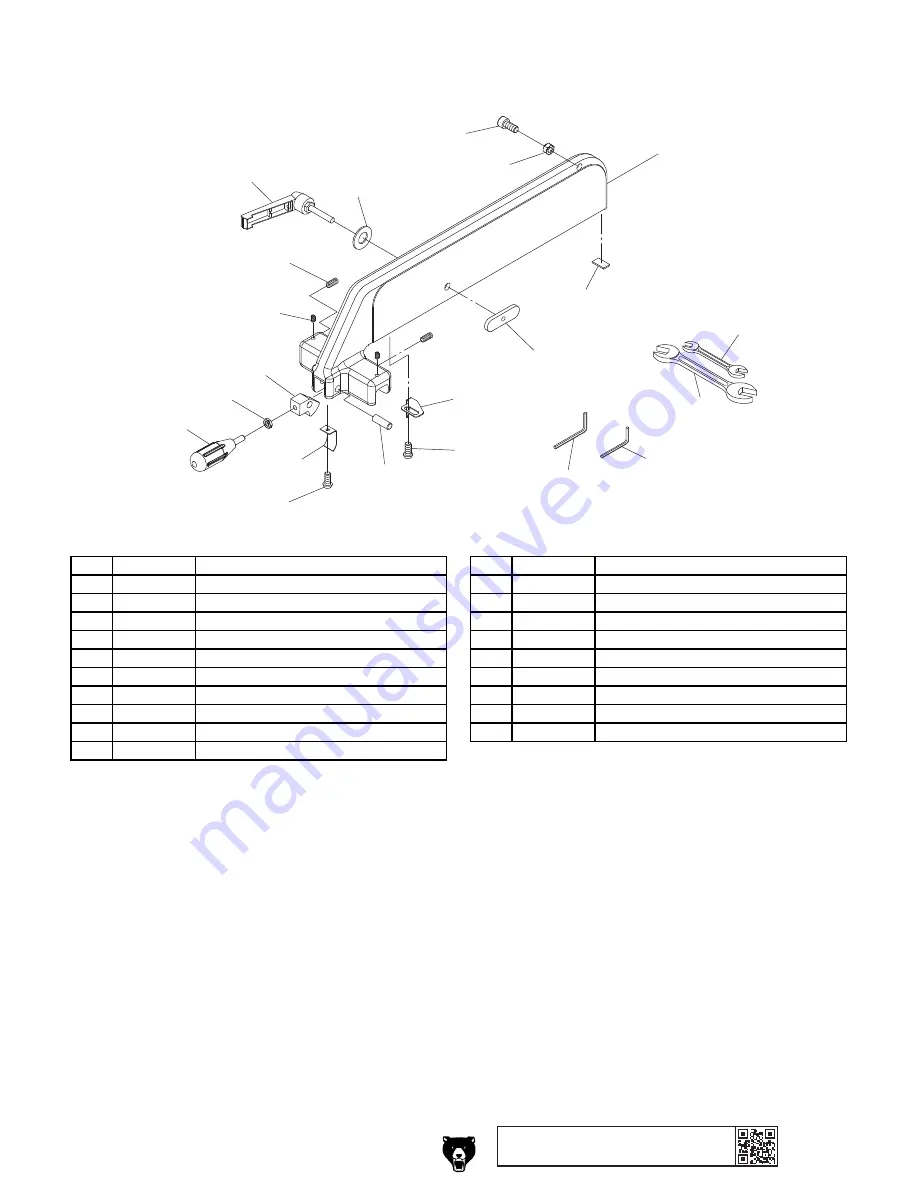
Fence Assembly & Tools

500

501

502

503

504

505

506

507

508

509

510

511

512

513

514

515

516

517

518

519

520

REF PART #

DESCRIPTION

REF PART #

DESCRIPTION

500

P0701500

LOCK LEVER M8-1.25 X 45

511

P0701511

SPRING PLATE

501

P0701501

FLAT WASHER 8MM

512

P0701512

FENCE HANDLE M8-1.25 X 20

502

P0701502

CAP SCREW M8-1.25 X 20

513

P0701513

HEX NUT M8-1.25

503

P0701503

HEX NUT M8-1.25

514

P0701514

LOCKING CLAMP

504

P0701504

FENCE

515

P0701515

SET SCREW NYLON M6-1 X 10

505

P0701505

NYLON PAD

516

P0701516

SET SCREW M8-1.25 X 12

506

P0701506

RESAW FENCE T-BAR

517

P0701517

WRENCH 10/13MM

507

P0701507

POINTER

518

P0701518

WRENCH 17/19MM

508

P0701508

FLANGE SCREW M5-.8 X 8

519

P0701519

HEX WRENCH 5MM

509

P0701509

SHAFT

520

P0701520

HEX WRENCH 6MM

510

P0701510

FLANGE SCREW M4-.7 X 8

Summary of Contents for G0701

Page 1: ...PRIL 2019 MN WARNING NO PORTION OF THIS MANUAL MAY BE REPRODUCED IN ANY SHAPE OR FORM WITHOUT THE WRITTEN APPROVAL OF GRIZZLY INDUSTRIAL INC BLTS12076 PRINTED IN TAIWAN MODEL G0701 19 ULTIMATE BANDSAW OWNER S MANUAL For models manufactured since 09 17 V3 04 19 ...

Page 2: ...ng grinding tool integrity and the usage of personal protective equipment The manufacturer will not be held liable for injury or property damage from negligence improper training machine modifications or misuse Some dust created by power sanding sawing grinding drilling and other construction activities contains chemicals known to the State of California to cause cancer birth defects or other repr...

Page 3: ...Operating Foot Brake 35 Table Tilt 35 Guide Post 36 Fine Tune Tracking 36 Blade Selection 37 Blade Selection Chart 40 Blade Breakage 41 Blade Care Break In 41 Changing Blade 42 Ripping 43 Crosscutting 43 Resawing 44 Cutting Curves 45 Stacked Cuts 45 SECTION 5 ACCESSORIES 46 SECTION 6 MAINTENANCE 48 Schedule 48 Wheel Brushes 48 Cleaning Protecting 48 Lubrication 48 Redressing Rubber Tires 51 SECTIO...

Page 4: ...want your feedback on this manual What did you like about it Where could it be improved Please take a few minutes to give us feedback Grizzly Documentation Manager P O Box 2069 Bellingham WA 98227 2069 Email manuals grizzly com Contact Info We are proud to provide a high quality owner s manual with your new machine We made every effort to be exact with the instruc tions specifications drawings and...

Page 5: ...uge K Table L 4 Side Dust Port M Lower Wheel Cover Lock Knob N Foot Brake O Fence Lock Lever P Blade Tension Quick Release Lever Q Blade Tracking Knob Lock Lever R Magnetic Switch S Table Tilt Handwheel T 4 Rear Dust Port U Lower Wheel Adjustment Hub V Main Motor W Table Tilt Lock Handle X Table Tilt Scale Y Blade Tension Handwheel To reduce your risk of serious injury read this entire manual BEFO...

Page 6: ...re moving upper blade guides with guide post elevation control or motor could burn out D Blade Tension Handwheel Tensions blade in gradual increments E Fence Used for ripping or resawing Distance from blade determines width of cut Can be used in vertical position as shown in Figure 1 for normal workpieces or in horizontal position for thin workpieces F Miter Gauge Lock Knob Secures angle position ...

Page 7: ...itch is reset Twist clockwise to reset Figure 3 Control panel O P Q K Blade Tension Quick Release Lever Adjusts blade tension for quick blade chang es L Blade Tracking Knob and Lock Lever Moves and locks blade tracking M Table Tilt Handwheel Tilts the table up to 5º to the left or 45º to the right N Table Tilt Lock Handle Locks or unlocks the table at the current angle Control Panel Rear Controls ...

Page 8: ...30V Single Phase 60 Hz Full Load Current Rating 22A Minimum Circuit Size 30A Connection Type Cord Plug Power Cord Included No Recommended Power Cord S Type 3 Wire 12 AWG 300VAC Plug Included No Recommended Plug Type L6 30 Switch Type Control Panel w Magnetic Switch Protection Lockout Key Motors Main Horsepower 5 HP Phase Single Phase Amps 22A Speed 1720 RPM Type TEFC Capacitor Start Induction Powe...

Page 9: ...Type Rack Pinion Floor to Table Height 35 1 4 in Fence Locking Position Front Fence is Adjustable for Blade Lead Yes Resaw Fence Attachment Included Yes Miter Gauge Included Yes Construction Materials Table Precision Ground Cast Iron Trunnion Cast Iron Fence Deluxe Extruded Aluminum Cast Iron Base Stand Pre Formed Steel Frame Body Pre Formed Steel Wheels Computer Balanced Cast Iron Tire Rubber Whe...

Page 10: ...d proof DANGEROUS ENVIRONMENTS Do not use machinery in areas that are wet cluttered or have poor lighting Operating machinery in these areas greatly increases the risk of accidents and injury MENTAL ALERTNESS REQUIRED Full mental alertness is required for safe operation of machin ery Never operate under the influence of drugs or alcohol when tired or when distracted For Your Own Safety Read Instru...

Page 11: ...moving parts or flying debris Make sure they are properly installed undamaged and working correctly BEFORE operating machine FORCING MACHINERY Do not force machine It will do the job safer and better at the rate for which it was designed NEVER STAND ON MACHINE Serious injury may occur if machine is tipped or if the cutting tool is unintentionally contacted STABLE MACHINE Unexpected movement dur in...

Page 12: ...oss of control If necessary use a jig or other work holding device WORKPIECE MATERIAL This machine is intended for cutting natural and man made wood products and laminate covered wood products This machine is NOT designed to cut metal glass stone tile etc HAND PLACEMENT Placing hands or fingers in line with blade during operation may result in serious injury if hands slip or workpiece moves unexpe...

Page 13: ...specially if connected to an undersized circuit To reduce the risk of these hazards avoid over loading the machine during operation and make sure it is connected to a power supply circuit that meets the specified circuit requirements Circuit Requirements for 230V This machine is prewired to operate on a power supply circuit that has a verified ground and meets the following requirements Nominal Vo...

Page 14: ...ded If you ever notice that a cord or plug is damaged or worn discon nect it from power and immediately replace it with a new one Serious injury could occur if you connect machine to power before completing setup process DO NOT connect to power until instructed later in this manual Grounding Instructions This machine MUST be grounded In the event of certain malfunctions or breakdowns grounding red...

Page 15: ...safe transport When unpacking separate all enclosed items from packaging materials and inspect them for shipping damage If items are damaged please call us immediately at 570 546 9663 IMPORTANT Save all packaging materials until you are completely satisfied with the machine and have resolved any issues between Grizzly or the shipping agent You MUST have the original pack aging to file a freight cl...

Page 16: ... Cleaner degreaser WD 40 works well Safety glasses disposable gloves Plastic paint scraper optional Basic steps for removing rust preventative 1 Put on safety glasses 2 Coat the rust preventative with a liberal amount of cleaner degreaser then let it soak for 5 10 minutes 3 Wipe off the surfaces If your cleaner degreas er is effective the rust preventative will wipe off easily If you have a plasti...

Page 17: ...cal Environment The physical environment where the machine is operated is important for safe operation and lon gevity of machine components For best results operate this machine in a dry environment that is free from excessive moisture hazardous chemi cals airborne abrasives or extreme conditions Extreme conditions for this type of machinery are generally those where the ambient temperature range ...

Page 18: ...ng Wood Blocks 1 With the help of another person to steady the load use the forklift to move the shipping pal let and bandsaw to its operating location 2 Remove the shipping crate from the pallet 3 Unbolt the bandsaw from the shipping pallet 4 Carefully position the forks of the forklift under the bandsaw head as shown in Figure 8 then place a 1x4 wood block between the head and the right fork and...

Page 19: ... setting or if it is permanently connect ed hardwired to the power supply local codes may require that it be anchored to the floor If not required by any local codes fastening the machine to the floor is an optional step If you choose not to do this with your machine we rec ommend placing it on machine mounts as these provide an easy method for leveling and they have vibration absorbing pads Numbe...

Page 20: ... dust port as shown in Figure 13 then secure them in place with hose clamps 2 Tug the hoses to make sure they do not come off Note A tight fit is necessary for proper performance DO NOT operate the Model G0701 without an adequate dust collection system This saw creates substantial amounts of wood dust while operating Failure to use a dust collec tion system can result in short and long term respir...

Page 21: ...3 Move the blade tension quick release lever all the way right as viewed from the rear of the machine to apply tension to the blade see Figure 14 Tension Handwheel Figure 14 Blade tension controls Quick Release Lever Tension Scale 4 Use the tension handwheel to bring the pointer on the tension scale to the appropri ate mark for the blade width Note Changes in the blade tension may change the blade...

Page 22: ...nob Lock Lever Note When the tracking knob is rotated the lower portion of the upper wheel will tilt out or in which affects the way the blade tracks 8 Spin the upper wheel with one hand and slowly adjust the tracking knob with the other until the blade rides in the center of the wheel tire without wandering 9 Tighten the lock lever to secure the setting then spin the upper wheel again to confirm ...

Page 23: ...st the side of the blade as illustrated in Figure 19 Figure 19 Squaring table to the blade 6 Use the table tilt handwheel to adjust the table square to the blade then move the tilt lock lever to the right to secure the setting 7 Adjust the positive stop bolt up until it just touches the table then re tighten the jam nut to hold it in place 8 Re check the table to make sure it is square to the blad...

Page 24: ...nd correct strange or unusual noises or vibrations before operating the machine further Always disconnect the machine from power when investigating or correcting potential problems OFF Button Figure 21 Resetting the OFF button 5 Push the OFF button in then twist it clock wise so it pops out When the OFF button pops out the switch is reset and ready for operation see Figure 21 Figure 22 Control pan...

Page 25: ...witch stops the flow of power to the machine It is the steady pressure on the foot brake that quickly brings the blade to a full stop 11 Start the machine then apply steady pres sure to the foot brake If the machine turns OFF and the blade comes to a rapid stop the foot brake sys tem is working properly If the machine does NOT turn OFF the foot brake system is not working correctly Immediately pre...

Page 26: ... adjusted blade guides and other bandsaw compo nents and using an appropriate feed rate Improper blade tension is unsafe produces inac curate and inconsistent results and introduces unnecessary wear on bandsaw components Over tensioning the blade increases the chance of the blade breaking or wheel misalignment Under tensioned blades wander excessively while cutting and will not track properly duri...

Page 27: ...Step 6 If blade deflects less than 1 4 it is over ten sioned Rotate blade tension handwheel counterclockwise two full turns and repeat Step 5 If blade deflects 1 4 or more blade is not properly tensioned Rotate blade tension handwheel clockwise to incrementally ten sion blade and repeat Step 5 until blade is properly tensioned 6 Adjust blade guides as described in Aligning Blade Support Bearings o...

Page 28: ... guide block cap screws to secure the support bearing position 7 Loosen the support bearing shaft adjustment bolt and the lateral rod adjustment bolt see Figures 24 25 8 Adjust the blade guide bearings until the edges of the bearings are 1 64 approximately the thickness of four pieces of paper behind the blade gullets as illustrated in Figure 27 Note With larger blades it may not be pos sible to r...

Page 29: ...Blade Guide Bearings beginning on Page 28 for detailed instructions Lower Blade Bearing 1 Make sure the blade is properly tensioned Page 24 and tracking correctly Page 19 2 DISCONNECT MACHINE FROM POWER 3 Open both wheel covers then familiarize yourself with the lower blade bearing controls shown in Figures 29 31 4 To adjust the lower blade bearings follow the same procedure used for the upper bla...

Page 30: ... and support bearings Make sure to firmly secure the blade guard in place when you have completed the adjustment 5 Loosen the rotation adjustment bolts on both sides of the blade see Figures 32 33 6 Rotate the knurled knobs see Figure 32 to position the bearings as close to the blade as possible without touching it Note Ideally the bearings should be approx imately 0 004 away from the blade which ...

Page 31: ...upper blade guide bearings on the previous page Aligning Table To align the table with the blade 1 Make sure the blade is properly tensioned Page 24 and tracking correctly Page 19 2 DISCONNECT MACHINE FROM POWER 3 Place the straightedge flat on the table and across the blade so that it lightly touches both the front and back of the blade without touch ing a tooth as shown in Figure 35 Figure 35 Ex...

Page 32: ...ews 3 of 4 shown Trunnion Cap Screws 3 of 4 shown Aligning Fence Figure 37 Fence even with the miter slot Items Needed Qty Hex Wrench 6mm 1 To align the fence with the table 1 Make sure the blade is properly tensioned Page 24 and tracking correctly Page 19 2 DISCONNECT MACHINE FROM POWER 3 Make sure the table is properly aligned with the blade as instructed in the previous sub section 4 If attache...

Page 33: ...ind against the table If the fence does bind against the table re loosen the rail cap screws and pull the rail away from the table then repeat Steps 7 8 To align the miter gauge body 1 Make sure the blade is properly tensioned Page 24 and tracking correctly Page 19 2 Install the widest blade possible and correctly tension it 3 DISCONNECT MACHINE FROM POWER 4 Lay the machinist s square flat on the ...

Page 34: ...hillips Head Screwdriver 1 After the fence is properly aligned with the table which is aligned with the blade the fence pointer must be calibrated to ensure quick and accurate positioning of the fence To calibrate the fence pointer 1 Make sure the blade is properly tensioned Page 24 2 DISCONNECT MACHINE FROM POWER 3 Position the fence against the left side of the blade so that it is touching the b...

Page 35: ...nual Read books magazines or get formal training before beginning any proj ects Regardless of the content in this sec tion Grizzly Industrial will not be held liable for accidents caused by lack of training To complete a typical operation the operator does the following 1 Examines workpiece to make sure it is suit able for cutting 2 Adjusts table tilt if necessary to correct angle of desired cut 3...

Page 36: ...This machine is intended for cutting natural and man made wood prod ucts laminate covered wood products and some plastics Cutting drywall or cementious backer board creates extremely fine dust and may reduce the life of the bearings This machine is NOT designed to cut metal glass stone tile etc cutting these materials with a bandsaw may lead to injury Foreign Objects Nails staples dirt rocks and o...

Page 37: ...adjust ment Disconnect power from the bandsaw before performing table adjust ments The bandsaw table will tilt 5 left and 45 right to provide a wide range of cutting options To tilt the table 1 DISCONNECT MACHINE FROM POWER 2 Loosen the table tilt lock handle shown in Figure 43 3 To tilt the table to the right turn the table tilt handwheel clockwise see Figure 43 Table Tilt 4 To tilt the table to ...

Page 38: ...h the clear window on the right side of the bandsaw as shown in Figure 45 Fine Tune Tracking Figure 45 Blade tracking window 3 Loosen the blade tracking lock lever 4 Using the tracking controls Page 5 Figure 2 adjust the blade so it tracks on the center of the wheel 5 Tighten the blade tracking lock lever NOTICE Adjusting the final blade tracking setting requires the machine to be turned ON 4 Pres...

Page 39: ...f teeth per inch measured from gullet to gullet Blade Width Cutting Radius 51 2 3 4 Figure 47 Recommended cutting radius per blade width Blade Length Measured by the blade circumference blade lengths are specific to each bandsaw They are determined by the wheel diameter and distance between the wheels Blades will vary slightly even in the same length because of how they are welded Refer to the Acc...

Page 40: ...s them dig into the material and the gullets are usually rounded for easier waste removal These blades are excellent for the tough demands of resawing and ripping thick material Raker Skip Hook Figure 48 Main blade tooth styles Tooth Set Two common tooth sets for wood bandsaw blades are alternate and raker Each different type of tooth set removes material in a different manner leaving cuts with di...

Page 41: ... Blade Material Bandsaw blades must meet two requirements flexibility and hardness The flexibility of a blade allows it to travel on the wheel as a band while hardness allows the teeth to cut and hold an edge Modern materials technology has allowed bandsaw blades to meet these requirements in various ways Carbon Steel These blades are differentially heat treated to provide hard teeth that will hol...

Page 42: ... M Crosscutting Thin Stock R H S F Crosscutting Thick Stock R H S M Crosscutting Round Stock R H S F M R H S F M Mitre Cut R H S F M Tenons R H S M R H S M Sharp Curves R H S F Gradual Curves R H S F M Key Tooth Type Tooth Pitch Teeth per Inch or TPI R H S R H S R H S F M C Hook Raker Skip Fine 14 32 TPI Medium 4 12 TPI Coarse 2 4 TPI Use the blade selection chart below as a general guide when sel...

Page 43: ...ce thickness The general rule of thumb is to have not less than two teeth in contact with the workpiece at all times during cutting Blade Care Break In Blade Care A bandsaw blade is a thin piece of steel that is subjected to tremendous strain You can obtain longer use from a bandsaw blade if you give it fair treatment and always use the appropriate feed rate for your operation Be sure to select bl...

Page 44: ...vers NOTICE When you change the blade or adjust the tension and tracking the spaces between the guide and support bearings will change In these cases you must adjust the upper and lower guide and support bearings before continuing with cutting operations Pages 25 28 Always disconnect power to the machine when changing blades Failure to do this may result in seri ous personal injury LACERATION HAZA...

Page 45: ... line of cut In the event that something unexpected happens your hands or fingers may slip into the blade ALWAYS use a push stick when ripping narrow pieces Failure to fol low these warnings may result in serious personal injury Ripping Crosscutting is the process of cutting across the grain of wood For plywood and other processed wood crosscutting simply means cutting across the width of the mate...

Page 46: ... the blade To resaw a workpiece 1 Verify that the bandsaw is set up properly and that the fence is parallel to the blade 2 Install the resaw fence set it to the desired width of cut and lock it in place 3 Adjust the upper blade guide so it is 1 4 1 above the workpiece with a minimum amount of blade exposed Figure 55 Example of resawing lumber Resawing see Figure 55 is cutting a workpiece into two ...

Page 47: ... 8 1 8 3 16 3 8 1 4 5 8 3 8 11 4 1 2 21 2 5 8 33 4 3 4 51 2 One of the benefits of a bandsaw is its ability to cut multiple copies of a particular shape by stacking a number of workpieces together Before making stacked cuts ensure that both the table and the blade are properly adjusted to 90 Pages 19 20 Otherwise any error will be compounded To complete a stacked cut 1 Align your pieces from top t...

Page 48: ...itional recommended accessories 168 Replacement Blades Model Width TPI Type Gauge H9575 1 2 3 Claw 0 025 H9576 1 2 4 Claw 0 025 H9577 1 2 6 Claw 0 025 H9578 1 2 10 Raker 0 025 H9579 1 3 Claw 0 035 H9580 1 4 Claw 0 035 H9581 1 10 Raker 0 035 H9582 11 4 3 4 Pitch 0 042 T25021 3 8 3 Raker 0 032 T25038 1 2 3 Raker 0 032 T25055 3 4 2 3 Claw 0 025 T25066 3 4 2 3 Raker 0 035 T25077 1 1 Raker 0 035 T25088...

Page 49: ...yday a half mask respirator can be a lifesaver Also compatible with safety glasses order online at www grizzly com or call 1 800 523 4777 Figure 59 Assortment of basic eye protection Basic Eye Protection T20501 Face Shield Crown Protector 4 T20502 Face Shield Crown Protector 7 T20503 Face Shield Window T20451 Kirova Clear Safety Glasses T20452 Kirova Anti Reflective S Glasses T20456 DAKURA Safety ...

Page 50: ...tecting Cleaning the bandsaw is relatively easy Vacuum excess wood chips and sawdust and wipe off the remaining dust with a dry cloth If any resin has built up use a resin dissolving cleaner to remove it Protect the unpainted cast iron surfaces on the table by wiping it clean after every use this ensures moisture from wood dust does not remain on bare metal surfaces Keep the table rust free with r...

Page 51: ...ncy As Needed To lubricate the blade guide rack and pinion 1 Lower the upper blade guide until it reaches the table 2 DISCONNECT MACHINE FROM POWER 3 Using a rag and mineral spirits wipe off any existing grease and sawdust buildup on the rack see Figure 63 Tension Adjustment Assembly Lubrication Type GL2 Grease or Equivalent Amount Thin Coat Frequency As Needed To lubricate the tension adjustment ...

Page 52: ...table tilt rack and pinion assembly 1 DISCONNECT MACHINE FROM POWER 2 With the table perpendicular to the blade and using a rag and mineral spirits wipe off all existing grease and sawdust buildup from the rack 3 Move the table up to its maximum 45 angle and wipe off all existing grease and sawdust buildup from the rack see Figure 65 Trunnion Lubrication Type GL2 Grease or Equivalent Amount Thin C...

Page 53: ...that point redressing will no longer be effective and the tires must be replaced Redressing Rubber Tires To redress the rubber tires 1 DISCONNECT MACHINE FROM POWER 2 Put on heavy leather gloves 3 Remove the blade 4 Clean any built up sawdust from the rubber tires 5 Hold 100 grit sandpaper against the rub ber tire and rotate the wheel by hand Only redress the rubber enough to expose a fresh rubber...

Page 54: ...adjust test replace brake switch 5 Allow relay motor to cool If necessary press reset button inside switch 6 Trace replace broken or corroded wires fix loose connections 7 Correct the wiring 8 Switch power supply on verify voltage 9 Wire motor correctly Refer to inside junction box cover on Page 69 10 Test all legs for power test field coil and fix contacts or replace if at fault 11 Replace reset ...

Page 55: ...ble Cause Possible Solution Machine stalls or slows when operating 1 Too much pressure when feeding workpiece 2 Workpiece too moist or material not suitable for machine 3 Workpiece is warped 4 Fence incorrectly adjusted 5 V Belt s slipping 6 Run capacitor at fault 7 Motor connection wired incorrectly 8 Motor overheated 9 Contactor has poor contacts or is at fault 10 Centrifugal switch at fault 11 ...

Page 56: ... tight inside cuts 5 Inspect replace blade Page 42 6 Adjust blade tracking Page 19 7 Adjust blade guide bearings for correct blade support 8 Adjust upper blade guides as close as possible to workpiece 9 Inspect replace blade Page 42 10 Replace or re install wheels 11 Align table miter slot and fence with blade Page 30 Blade wears on one side slows smokes or shows overheating 1 Blade contacting tab...

Page 57: ...when not in use 8 Replace wheels The cut is crooked or the blade wanders blade lead 1 The feed pressure is too high or the blade speed is too slow 2 The blade tension is low 3 The blade is dull or damaged 4 Inadequate blade support 5 Incorrect blade for application 6 The blade tracking is wrong 7 Table is loose 8 Fence or miter slot out of alignment with blade 9 Blade guide alignment at fault 1 Ad...

Page 58: ... amount of deflection see Figure 67 If deflection is more than 1 8 tension the V belt Pulley Deflection Pulley Figure 67 V belt deflection Tensioning V Belts 1 DISCONNECT MACHINE FROM POWER 2 Open the wheel covers 3 Loosen the motor adjustment screws shown in Figure 68 4 Adjust the V belt tension If the belt is too loose turn the tension nut clockwise to tighten the belts If the V belt is too tigh...

Page 59: ...rake shoe If the brake pad thickness measures 1mm or less then it needs to be replaced Follow the instructions in Replacing Brake Shoe on Page 63 to replace it 8 Place the new V belts onto the lower wheel pulley 9 Slide the wheel all the way towards the back of the machine then secure it with the cap screw and flat washer removed in Step 5 10 Roll the new V belts onto the motor pulley Note Replace...

Page 60: ...arallel to the long edge 2 Slide the bandsaw fence out of the way and cut halfway through the board on the line by pushing it into the blade Turn the bandsaw OFF and wait for the blade to stop 3 Clamp the board to the bandsaw table with out moving it Now slide the fence over to the board so it barely touches one end of the board 4 Loosen the three cap screws that secure the fence rail to the under...

Page 61: ...plate where it was attached pre viously and down until it contacts the wheel block plate then back the screw off two full turns see Figure 72 6 Tighten the jam nut Figure 72 Quick release tension lever adjustment screw Tension Adjustment Screw Jam Nut Brushes Figure 71 The wheel brush and blade brushes Adjusting Wheel Blade Brushes The lower wheel compartment contains the brush es shown in Figure ...

Page 62: ...re 73 Squaring table to blade 5 Adjust the table square to the blade using the table tilt handwheel then secure it with the table tilt lock handle 6 Re connect the machine to power and lower the guide post to within 1 of the table top tighten the guide post lock knob to hold it in place 7 Disconnect the machine from power then place a machinist s square on the table next to the right hand side of ...

Page 63: ...5 enough to fit metal shims wide enough to fit the full width of the guide bracket between the frame and the guide post bracket see Figure 78 Shim B Left Side View Shim A Frame Blade Guide Post Guide Bracket Figure 78 Location for placing shims Shim thickness not drawn to scale Figure 76 Guide block cap screws blade guard removed for photo clarity Guide Block Cap Screws 4 Remove the two cap screws...

Page 64: ...ith the guide post assembly closer to the table 13 Re install the blade guide assembly 14 Re install the blade and the table pin then close the wheel covers 15 Check the blade tension refer to Page 24 and tracking refer to Page 19 16 Perform the Aligning Blade Bearings and Adjusting Blade Guide Bearings proce dures on Pages 25 and 28 If the guide post motor ever needs to be replaced contact our Te...

Page 65: ...acement brake shoe Part P0701059 refer to Page 73 Items Needed Replacement Brake Shoe Part P0701059 1 Hex Wrench 5mm 1 Hex Wrench 6mm 1 Wrench 10mm 1 Wrench 17mm 1 To replace the brake shoe 1 DISCONNECT MACHINE FROM POWER 2 Follow Steps 1 7 in Replacing V Belts on Page 57 4 Install a new brake shoe onto the brake lever with the cap screws lock washers and bush ings removed in Step 3 5 Re install t...

Page 66: ...racking Items Needed 70 Long 2x4 1 Hex Wrenches 5 6 8mm 1 Ea Wrenches 10 17mm 1 Tape Measure 1 Coplanarity Gauge 1 Straightedge Fine Ruler 1 Checking Coplanarity 1 Make the Coplanarity Gauge shown in Figure 81 Note For best results straighten the edges of the 2x4 with a jointer before cutting 2 DISCONNECT MACHINE FROM POWER 3 Remove the fence and open both wheel cov ers 4 Adjust the blade guides a...

Page 67: ...ance measured in Step 3 and place them on the wheel shaft 6 Replace the upper wheel the original wash ers the securing screw and the blade 7 Tighten the blade then check the wheels with the coplanarity gauge Wheel coplanarity changes as the blade is tightened so it is best to check the wheel alignment when the blade is tensioned as it would be for normal operations 8 When the wheels are coplanar p...

Page 68: ...st the lower wheel 1 DISCONNECT MACHINE FROM POWER 2 Loosen the jam nuts on the lower wheel adjustment hub see Figure 85 3 Loosen one tilt adjustment hex bolt then tighten the opposing hex bolt approximately an equal amount 4 Check the wheels with the coplanarity gauge then adjust the lower wheel at the hub as needed until it is parallel and coplanar with the top wheel 5 Tighten the jam nuts to lo...

Page 69: ...t at the time of printing but may not match your machine If you find this to be the case use the wiring diagram inside the motor junction box CAPACITORS INVERTERS Some capacitors and power inverters store an electrical charge for up to 10 minutes after being disconnected from the power source To reduce the risk of being shocked wait at least this long before working on capacitors EXPERIENCING DIFF...

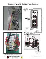
Page 70: ... B C Front View D E F G H 230 VAC 1 PH A B C D E F G H Description Wiring Diagram Page Reference A Power Junction Box 69 B Magnetic Switch 69 C Motor Junction Box 69 D Control Panel 70 E Guide Post Elevation Control 70 F Upper Door Safety Switch 71 G Guide Post Elevation Motor 71 H Brake Switch 71 ...

Page 71: ... 13 SDE 14 SDE MA 30 230V G X Y Ground Hot Hot L6 30 Plug As Recommended Power Junction Box Magnetic Switch U V E Motor Junction Box A B C R R S Ground Ground Ground Ground Start Capacitor 300M 250V Run Capacitor 45M 450V S E E 18 26 AMP RESET 96 98 1 2 3 4 5 6 95 18 22 26 RESET SDE RA 30 A A2 V U Contactor Figure 86 Magnetic switch wiring To Control Panel Page 70 ...

Page 72: ...rol panel wiring Figure 88 Guide post elevation control wiring Control Panel 22 14 21 13 Key Switch 22 14 21 13 22 14 21 13 ON STOP Switch Down Lamp Up Lamp Transformer Guide Post Elevation Control D E 5A 50 5A 50 To Guide Post Elevation Motor Page 71 To Brake Switch Page 71 To Door Safety Switch Page 71 To Magnetic Switch Page 69 ...

Page 73: ... diagrams 3 Upper Door Safety Switch 24 12 23 11 Guide Post Elevation Motor C NO NC Brake Switch F G H To Control Panel Page 70 To Guide Post Elevation Control Page 70 To Control Panel Page 70 Figure 89 Upper door safety switch wiring Figure 90 Guide post elevation motor wiring Figure 91 Brake switch wiring ...

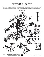
Page 74: ...22 27 28 31 155 153 154 157 156 41 42 43 44 45V2 46 47 151 152 158 50 45V2 1 45V2 2 45V2 3 45V2 4 45V2 5 45V2 6 45V2 7 45V2 8 45V2 9 45V2 10 3 37 35 49 57 58 59 60 61 62 63 64 65 66 67 55 56 66 71 72 73 43 40 70 68 69 41 80 81 82 83 84 85 86 87 88 89 90 62 63 61 Frame SECTION 9 PARTS We do our best to stock replacement parts when possible but we cannot guarantee that all parts shown are available ...

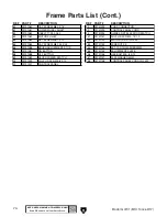
Page 75: ... OL RELAY SDE RA 30A 18 26A 19 P0701019 LEVER HUB 53 P0701053 CORD CLAMP 1 2 20 P0701020 CAP SCREW M10 1 5 X 20 54 P0701054 BRAKE PEDAL 21 P0701021 LOCK WASHER 10MM 55 P0701055 LOCK WASHER 6MM 22 P0701022 STAR KNOB BOLT M10 1 5 X 55 56 P0701056 CAP SCREW M6 1 X 16 23 P0701023 LEVER 57 P0701057 LOCKING SET SCREW M7 1 X 10 24 P0701024 FLAT WASHER 10MM 58 P0701058 BUSHING 25 P0701025 CLEAR PLASTIC WI...

Page 76: ...ST ELEVATION SWITCH 83 P0701083 MOTOR PULLEY 151 P0701151 PHLP HD SCR M4 7 X 10 84 P0701084 SET SCREW M6 1 X 12 152 P0701152 MOTOR CORD 12G 3W 85 P0701085 CAP SCREW M8 1 25 X 25 153 P0701153 WIRE NUT P3 86 P0701086 BRUSH ADJUSTMENT STUD 154 P0701154 EXT TOOTH WASHER 5MM 87 P0701087 ON BUTTON 155 P0701155 ADJUSTMENT PLATE 88 P0701088 OFF BUTTON 156 P0701156 HEX BOLT M5 8 X 12 89 P0701089 KEYED POWE...

Page 77: ...els 100 101 102 103 104 105 106 107 108 109 110 111 112 113 114 116 117 118 119 103 110 104 115 111 110 108 109 110 112 113 114 127A 129 130 131 132 117 118 119 120 124 120 119 117 118 119 117 133 134 135 136 137 138 139 140 141 142 143 144 145 146 147 148 149 150 121A 120 120 124 126 128 123 122 123 122 ...

Page 78: ...GE 135 P0701135 CAP SCREW M8 1 25 X 30 110 P0701110 CAP SCREW M5 8 X 12 136 P0701136 BRACKET 111 P0701111 DOOR HANDLE 137 P0701137 CAM 112 P0701112 CAP SCREW M6 1 X 16 138 P0701138 FLAT HD SCR M5 8 X 16 113 P0701113 LOCK WASHER 6MM 139 P0701139 TENSION ADJUSTMENT BOLT 114 P0701114 LOCK NUT M6 1 140 P0701140 GUIDE BLOCK 115 P0701115 LOWER WHEEL DOOR 141 P0701141 COMPRESSION SPRING 116 P0701116 SAW ...

Page 79: ...RAIL PLATE 233 P0701233 TABLE BASE 208 P0701208 FLAT WASHER 6MM 234 P0701234 TRUNNION T NUT 209 P0701209 LOCK WASHER 6MM 235 P0701235 POINTER 210 P0701210 HEX BOLT M6 1 X 20 236 P0701236 PHLP HD SCR M4 7 X 10 211 P0701211 HEX BOLT M8 1 25 X 20 237 P0701237 TRUNNION HANDLE M12 1 75 212 P0701212 LOCK WASHER 8MM 238 P0701238 HANDLE SHAFT 213 P0701213 FLAT WASHER 8MM 239 P0701239 HEX NUT M12 1 75 214 ...

Page 80: ... Assembly 311 312 313 314 315 316 317 318 319 320 321 322 323 324 325 326 327 328 329 330 331 332 333 334 335 336 337 338 340 361 362 363 364 365 366 367 368 300 301 302V2 303 304 306 307 308 309 310 301 307 308 338 341 342 343 344 345 346 348 352 353 358 359 360 349 350 351 342 335 338 340 341 342 343 344 348 345 346 362 363 365 366 355 356 Guide Post Elevation Assembly 369A ...

Page 81: ...PINION GEAR 349 P0701349 LOWER GUIDE BLOCK BRACKET 316 P0701316 SHOULDER BOLT 350 P0701350 FLAT WASHER 6MM 317 P0701317 PROTECTIVE PLATE 351 P0701351 CAP SCREW M6 1 X 16 318 P0701318 HEX NUT M5 8 352 P0701352 STEPPED BUSHING 319 P0701319 PROTECTIVE COVER 353 P0701353 UPPER GUIDE BLOCK BRACKET 320 P0701320 FLANGE BOLT M5 8 X 10 355 P0701355 CAP SCREW M8 1 25 X 35 321 P0701321 CAP SCREW M8 1 25 X 16...

Page 82: ... X 16 418 P0701418 COMPRESSION SPRING 404 P0701404 UPPER GUIDE POST 419 P0701419 SET SCREW M10 1 5 X 10 405 P0701405 GUIDE POST MOTOR 40W 12VDC 420 P0701420 NYLON SET SCREW M7 1 X 10 406 P0701406 FLAT HD SCR M5 8 X 16 421 P0701421 SET SCREW M4 7 X 8 407 P0701407 MOTOR MOUNT 422 P0701422 LOCK COLLAR 408 P0701408 WORM SHAFT 423 P0701423 SET SCREW M4 7 X 6 409 P0701409 ELEVATION GEAR HOUSING 424 P070...

Page 83: ...R 8MM 512 P0701512 FENCE HANDLE M8 1 25 X 20 502 P0701502 CAP SCREW M8 1 25 X 20 513 P0701513 HEX NUT M8 1 25 503 P0701503 HEX NUT M8 1 25 514 P0701514 LOCKING CLAMP 504 P0701504 FENCE 515 P0701515 SET SCREW NYLON M6 1 X 10 505 P0701505 NYLON PAD 516 P0701516 SET SCREW M8 1 25 X 12 506 P0701506 RESAW FENCE T BAR 517 P0701517 WRENCH 10 13MM 507 P0701507 POINTER 518 P0701518 WRENCH 17 19MM 508 P0701...

Page 84: ...of oil resistant material COPYRIGHT GRIZZLY INDUSTRIAL INC FOR GRIZZLY MACHINES ONLY DO NOT REPRODUCE OR CHANGE THIS ARTWORK WITHOUT WRITTEN APPROVAL Grizzly will not accept labels changed without approval If artwork changes are required contact us immediately at manuals grizzly com To reduce risk of death or serious injury read manual BEFORE using machine To get a new manual call 800 523 4777 or ...

Page 85: ......

Page 86: ......

Page 87: ...r for incidental contingent special or consequential damages arising from the use of our products The manufacturers reserve the right to change specifications at any time because they constantly strive to achieve better quality equipment We make every effort to ensure that our products meet high quality and durability standards and we hope you never need to use this warranty In the event you need ...

Page 88: ......

Reviews: