-20-
Model G0726 (Mfg. Since 7/11)
Assembly
To assemble the mill:
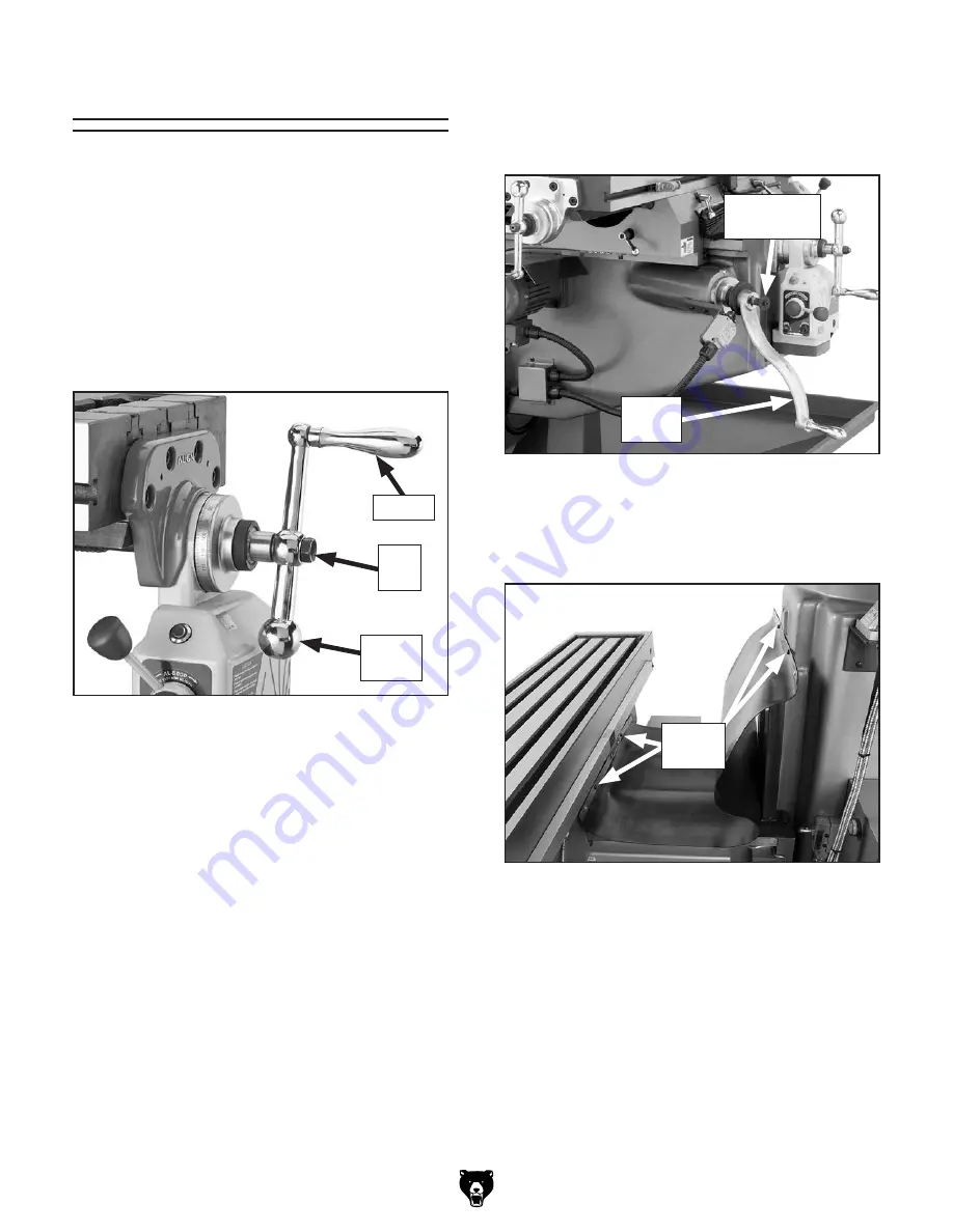
1. Remove pre-installed hex nuts from
leadscrew ends, align ball handle keyways
with leadscrew keys as you slide ball handles
on, then secure them with hex nuts (see
Figure 9).
Note: Tighten hex nuts just until they are snug.
Overtightening could increase the wear of
moving parts.
2. Thread handles into small end of the ball
handles and tighten them with 14mm wrench.
3. Remove cap screw and spacer from Z-axis
leadscrew end, slide crank onto shaft as
shown in
Figure 10, then re-install cap screw
and spacer.
4. Move table all the way forward, then attach
rear way cover with the four pre-installed cap
screws, as shown in
Figure 11.
Figure 10. Z-axis crank installed.
Z-Axis
Crank
Cap Screw
& Spacer
Figure 11. Rear way cover installed (digital
readout scale cover removed).
Cap
Screws
Figure 9. Ball handle installed
(1 of 3).
Hex
Nut
Handle
Ball
Handle


