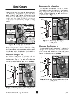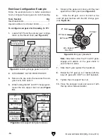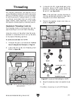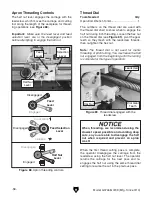
Model G0746/G0749 (Mfg. Since 3/13)
-53-
power feed controls
Use
figures 74–75 and the following descriptions
to understand the power feed controls.
Note: Before using power feed, you may have to
re-configure the end gears, depending on how
they are set up. Refer to
End Gears on Page 55
for detailed instructions.
D. Quick-change Gearbox feed Dial and
Levers: position these as indicated on the
charts to choose different feed rates for
metric and inch threading or diametral and
modular pitches.
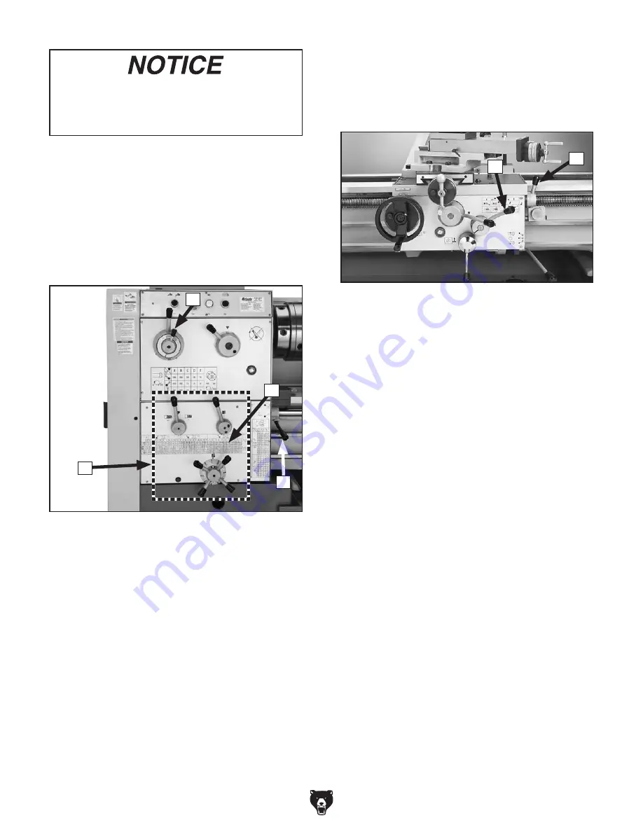
figure 74. power feed controls on the
headstock.
d
To avoid damaging the lathe, ALWAyS make
sure the spindle is completely stopped
bEfORE using the headstock controls to
make changes.
A. feed Direction Lever: selects the direction
for power feed. When the lever is positioned
as shown in
figure 74, the carriage will move
to the right along the bed, or the cross feed
will travel toward the front of the lathe.
b. feed Rate chart: displays the settings for
the quick-change gearbox dial and levers
for the selected feed rate. refer to
Setting
power feed Rate subsection on the next
page for detailed instructions.
c. Leadscrew feed Rod Selection Lever:
When the lever is down, enables feed rod
movement, thereby allowing powered car-
riage movement. When lever is up, enables
leadscrew for threading or pitch turning.
a
E. feed Lever: When the lever is down, enables
carriage for power feed operations. When the
lever is up, disables power feed and enables
threading operations.
f. feed Selection Lever: Changes the power
feed to either the cross slide or the carriage.
When the lever is up, the cross slide is select-
ed. When the lever is down, the carriage is
selected. in the middle position neither the
cross slide nor the carriage will move.
Note: When using this lever, you may need
to slightly rotate the handwheel of the com-
ponent you are trying to engage, so that the
apron gears can mesh.
figure 75. apron power feed controls.
E
F
B
C

