-52-
Model G0750GV (Mfd. Since 03/18)
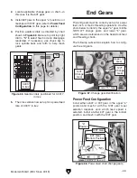
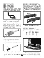
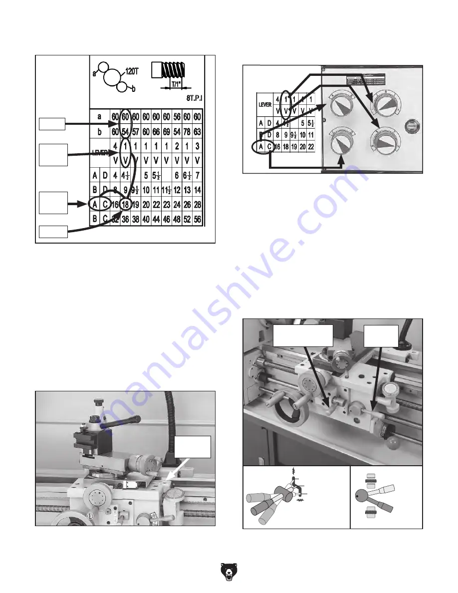
Figure 75. 18 TPI and corresponding dial
positions.
4. Locate A and C to the left of 18 TPI and find
1 and V above it.
Note:
In the next step, use the chuck key to
rock the spindle back-and-forth to help mesh
the gears as you make adjustments.
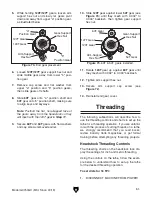
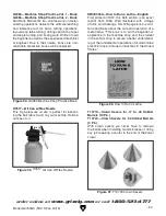
6. Position gearbox dials, as shown in
Figure 77.
Figure 77. Gearbox dial settings for 18 TPI.
The lathe is now set up to cut 18 TPI threads.
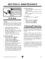
Apron Threading Controls
The half-nut lever engages the carriage with the
leadscrew, which moves the carriage and cutting
tool along the length of the workpiece for thread-
ing operations (see
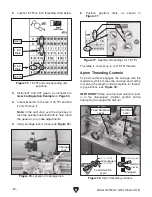
Figure 78).
IMPORTANT: Make sure the feed selection lever
is in the disengaged (middle) position before
attempting to engage the half nut.
Figure 78. Apron threading controls.
Cross Slide
Disengaged
Feed Selection
Lever
Carriage
Engaged
Half-Nut
Lever
Disengaged
Feed Selection
Lever
Half-Nut
Lever
3. Install 60T and 54T gears, as instructed in
Gear Configuration Example on Page 50.
2. Locate 18 TPI on inch threading chart below.
1 & V
Dials
18 TPI
A & C
Dials
Gears
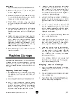
Figure 76. Location of carriage lock.
Carriage
Lock
5. Verify carriage lock is loose (see Figure 76)
Summary of Contents for G0750GV
Page 116: ......


