-26-
Model G0764Z (Mfd. Since 10/15)
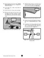
Figure 22. Sliding table T-bolt access on rear
side at front of saw.
Sliding Table T-bolt
Figure 23. Sliding table middle T-bolt access.
Sliding Table T-bolt
(Middle)
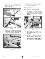
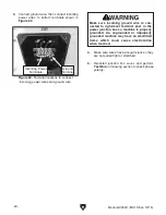
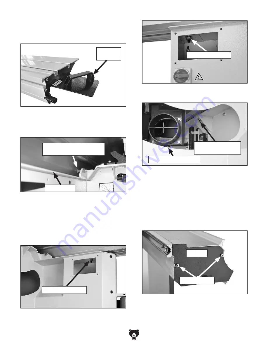
8. Attach end cap (as shown in Figure 24) with
Phillips screws already threaded into those
same holes on the sliding table.
Figure 24. End cap secured on sliding table with
Phillips screws.
Phillips Screws
End Cap
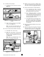
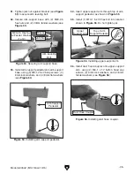
4. Install end plate with handle, as shown in
Figure 19, using the screws pre-installed in
this location on the sliding table
.
Figure 19. Slide table control end handle.
End Plate
w/Handle
6. Remove access covers on each side of the
frame to reach the T-bolts on the ends of the
sliding table (
Figures 21–22). Reach through
cabinet access hole to reach middle sliding
table T-bolt (
Figure 23).
Figure 21. Sliding table T-bolt access on rear
side at back of saw.
Sliding Table T-Bolt
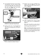
5. Position sliding table against parallelism
adjustment bolts at each end (see
Figure 20).
Figure 20. Sliding table parallelism adjustment
bolt (1 of 2).
Parallelism Adjustment Bolt
(1 of 2)
Sliding Table
7. Put (3) M12-1.75 hex nuts, (3) 12mm lock
washers, and (3) 12mm flat washers on end
of each T-bolt and tighten to secure sliding
table to frame (as shown in
Figures 21–23).
Cabinet Access Hole
Summary of Contents for G0764Z
Page 21: ...Model G0764Z Mfd Since 10 15 19 5mm Hardware Recognition Chart ...
Page 118: ......


