-48-
Model G0768/G0769 (Mfd. Since 8/15)
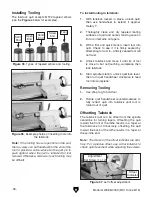
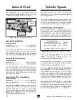
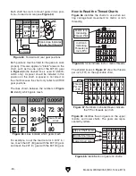
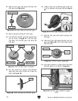
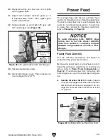
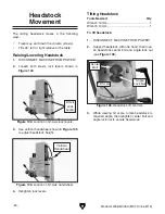
4. Move top V-belt to A position (see Figure 58)
to select low speed range (50–1000 RPM).
5. Re-tension V-belt (refer to "Tensioning
V-Belts" on
Page 81).
6. Re-install end cover.
7. Reset Emergency Stop button.
8. Rotate spindle direction switch to "F" or "R",
and press ON button.
9. Rotate spindle speed dial clockwise until
spindle speed display reads 100 RPM.
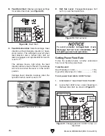
Figure 58. V-belt positioned in low speed range.
A
B
M
Low
High
Top
V-Belt
Understanding Gear
Charts
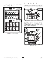
This subsection explains how to understand the
feed and thread charts on the headstock. If you do
not understand lathe gear charts, or need a quick
refresher, read this before configuring the end
gears for power feeding or threading operations.
0.0037"
84
20
A
A
40
in/
mm
n/1"
C
C
D
D
B
B
E
E
F
A
C D
B
E F
A
C D
B
E F
F
80
80
0.40
1.25 1.50 1.75 2.00 2.50 3.00
55
80
80
53
71
7163
57
71
71
63
33 3060 40
40
50
60
84
80
50
60
20
80
80
80
63
63
80
60
70
70
70
57
72
80
80
30
33 53 30 60 40 40
40
30
33
70
0.50 0.60 0.70 0.80 1.00
80
30 72
33 80
30
0.0068"
A
C D
B
E F
A
C D
B
E F
30
19 20 22 24 32 40 44
80 80
30
33 40
65
70
80 60
60
60
60
63
63
53
9 10 11 12 13 14 16 18
50
50
55
80
80
80
80
80
8060
60
7153 55
33
30
55
55
4030
53
53
53 72
63
70
57
57 72
72
72
72 80
70 40
40
40
63
57
55
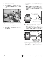
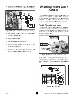
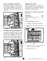
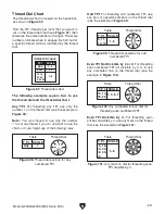
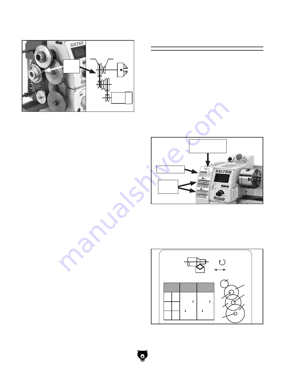
Figure 60. Feed chart.
Feed Chart—Displays headstock end gear posi-
tions for different speeds of automatic feed (power
feed) used with turning operations (see
Figure
60).
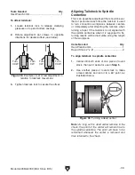
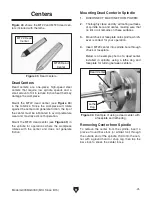
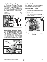
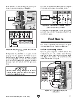
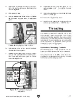
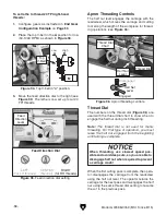
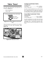
Figure 59. Feed and thread charts label.
Feed & Thread Charts Label
The feed and thread charts label (see
Figure 59)
provides information for setting up end gears for
threading or non-threading operations. The top
displays a feed chart, the bottom displays metric
and inch thread charts.
Feed & Thread
Charts Label
Feed Chart
Thread
Charts

