Model G0768/G0769 (Mfd. Since 8/15)
-55-
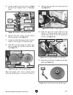
20. Re-install e-clips and hex nuts onto middle
and top gear shafts.
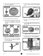
21. Adjust lash between meshed gears so it
is approximately 0.003", then tighten gear
shafts and fasteners.
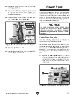
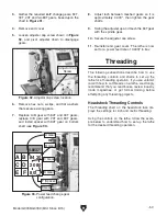
22. Swing adjuster up and mesh 53T gear with
40T spindle gear (see
Figure 86).
23. Secure adjuster cap screw.
24. Re-install end gear cover. The end gears are
now configured for 20 TPI.
Figure 86. 53T gear meshed with spindle gear.
Adjustor Cap
Screw
Spindle Gear
53T Gear
Power Feed
The carriage has power feed (or automatic feed)
options for threading or non-threading operations.
This section describes how to use the power feed
option for non-threading operations. To learn how
to power the carriage for threading operations,
refer to
Threading on Page 58.
Power Feed Controls
Use the following descriptions and figures to
understand the power feed controls.
Before using power feed, you may have to recon-
figure the end gears, depending on how they are
set up (refer to
Power Feed Configuration on
Page 52). The lathe comes from the factory with
the end gears set up in the power feed configura-
tion.
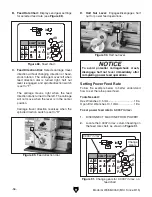
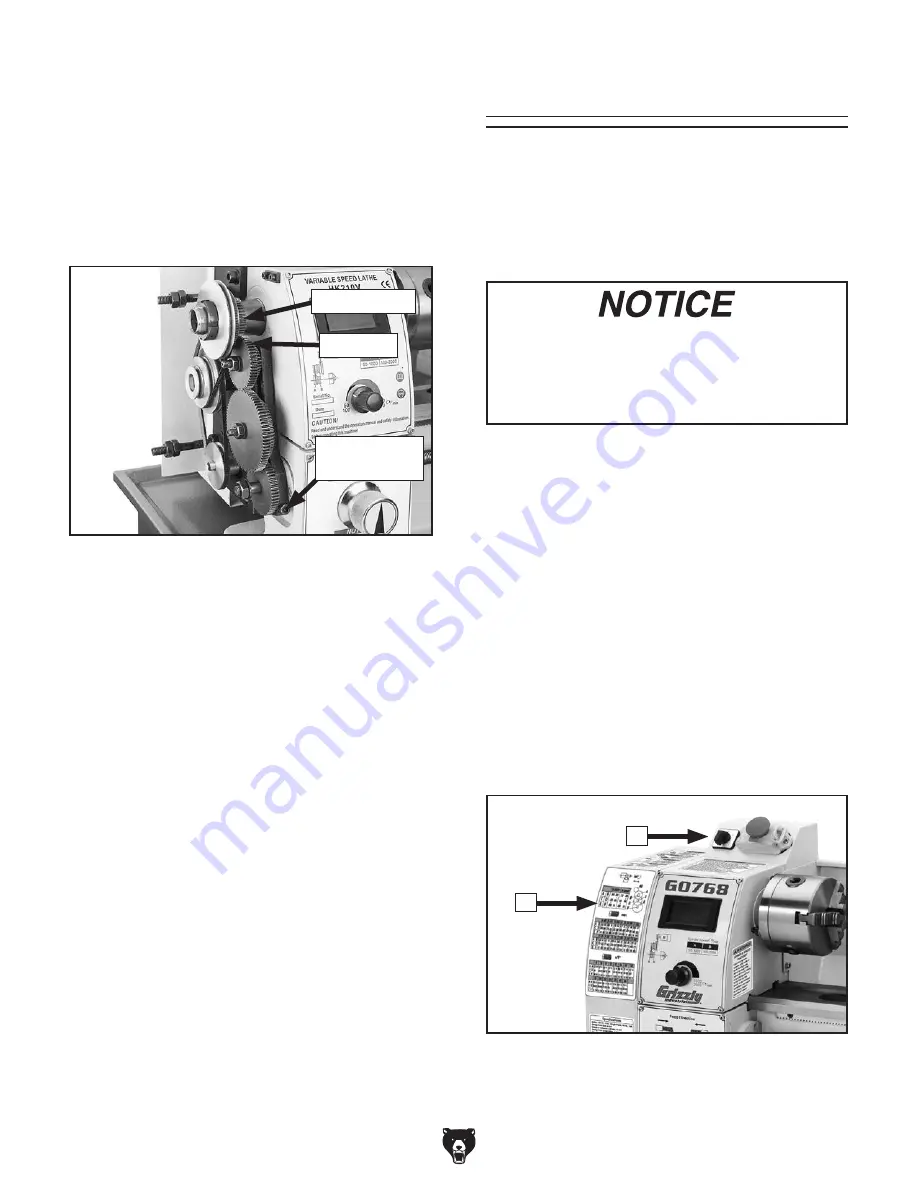
A. Spindle Direction Switch: Enables forward
or reverse carriage travel when feed direction
dial and half nut lever are engaged. The car-
riage will not move when the switch is in the
"0" position.
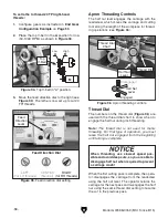
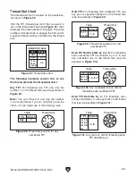
Figure 87. Spindle switch and feed rate chart.
A
B
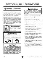
To avoid damaging lathe, NEVER allow
cutting tool to run into chuck! ALWAYS
make sure spindle is completely stopped
BEFORE using headstock controls to make
changes.

