background image

G0792 Update (Mfd. Since 04/18)

-3-

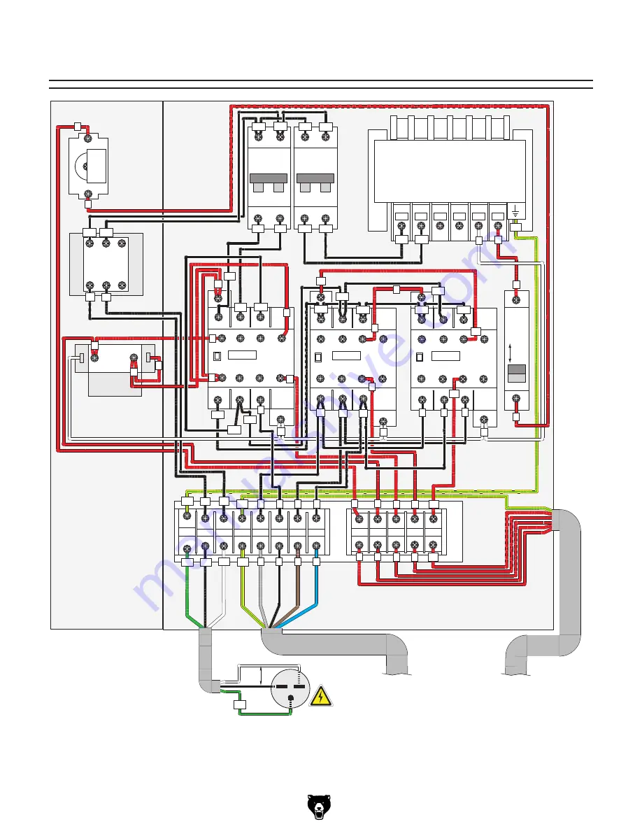
Electrical Panel Wiring Diagram

6-15 Plug

Hot

Hot

Ground

220

VAC

G

Transformer

1L1

22E

ON

OFF

QM1

C3

  CHNT

DZ47-60

3L2

5L3

43NO

31NC

21NC

13NO

14NO

22NC

32NC

44NO

6T3

4T2

CHNT

Beijing AOHENGDA Electric Co.

JB/T5555  50/60 HZ  T40/E IP2LX

Type: JBK5-63VA

TC

0

220 400 415

0

24

L1

L2

PE

U1

V2

W1

L1

L2

PE

U1

V2

W1

V1

V1

PE

2T1

1L1

22E

3L2

5L3

43NO

31NC

21NC

13NO

14NO

22NC

32NC

44NO

6T3

4T2

2T1

1L1

22E

SIEMENS 3TB41 24V

KM2

3L2

5L3

43NO

31NC

21NC

13NO

14NO

22NC

32NC

44NO

6T3

4T2

2T1

QF3

CHNT

CHNT

QF1

QF2

DZ47-60

DZ47-60

D10

C3

PE

L2

3

4

6

7

L1

PE

E-STOP

Button

1NC

Master 

POWER Switch

E&E LW8GS-

25/30000-A

PE

PE

3

3

R1

S1

4

4

4

6

6

1U1

1U1

1U1

1U1

1U1

1V1

1V1

1V1

11

11

8

8

1

1

7

7

10

10

L1

L1

L2

L2

T1

T2

T3

L1

L2

L3

1L1 1L2

1L1

1L2

1L2

1L1

2L1

2L2

2L2 2L1

0

0

0

R1

S1

PE

Anivec 

LA158-

BE102

2

2

Relay

Relay

PE

PE

3

4

6

7

10

3

4

6

7

10

10

Contactor

KM1

Contactor

SIEMENS 3TB41 24V

SIEMENS 3TB41 24V

Contactor

0

5

5

A2

A2

A2

A1

A1

A1

1

2

Anivec 

LA158-BW

3

4

X1

X2

NO

POWER

Button

5

5

5

0

1

5

1

5

0

6

5

5

1

6

1

6

6

4

4

4

1V1

1V1

To Motor

Page 30

To Foot Pedal & E-Stop

Page 30

(Replaces Page 29 in Owner's Manual)

Summary of Contents for G0792

Page 1: ...For questions or help with this product contact Tech Support at 570 546 9663 or techsupport grizzly com Model G0792 IMPORTANT UPDATE For Machines Mfd Since 04 18 and Owner s Manual Revised 03 16 COPYRIGHT MAY 2022 BY GRIZZLY INDUSTRIAL INC WARNING NO PORTION OF THIS MANUAL MAY BE REPRODUCED IN ANY SHAPE OR FORM WITHOUT THE WRITTEN APPROVAL OF GRIZZLY INDUSTRIAL INC SS22340 PRINTED IN CHINA Revised...

Page 2: ... cabinet components Figure 32 Foot pedal assembly emergency stop button and forward facing controls Figure 31 Foot pedal wiring Emergency Stop Button Foot Pedal Controls Emergency Stop Button Master Power Switch Power Button Relay Transformer Contactor Terminal Figure 33 Motor junction box and starting switch ...

Page 3: ... 21NC 13NO 14NO 22NC 32NC 44NO 6T3 4T2 2T1 QF3 CHNT CHNT QF1 QF2 DZ47 60 DZ47 60 D10 C3 PE L2 3 4 6 7 L1 PE E STOP Button 1NC Master POWER Switch E E LW8GS 25 30000 A PE PE 3 3 R1 S1 4 4 4 6 6 1U1 1U1 1U1 1U1 1U1 1V1 1V1 1V1 11 11 8 8 1 1 7 7 10 10 L1 L1 L2 L2 T1 T2 T3 L1 L2 L3 1L1 1L2 1L1 1L2 1L2 1L1 2L1 2L2 2L2 2L1 0 0 0 R1 S1 PE Anivec LA158 BE102 2 2 Relay Relay PE PE 3 4 6 7 10 3 4 6 7 10 10 ...

Page 4: ...arting Switch 4 4 3 3 2 2 1 1 6 4 4 1 1 5 5 To Control Panel Page 29 To Control Panel Page 29 Foot Pedal E Stop Diagram Replaces Page 30 in Owner s Manual 1 NC 2 3 4 ZB2 BE102 Ground PE GND Foot Pedal Controls E Stop Button 6 6 10 7 PE 220V Motor Start Capacitor CD60 100uF 275VAC 8 9 7 8 Run Capacitor CBB60 40uF 450VAC ESS1 41 Starting Switch 4 4 3 3 2 2 1 1 6 4 4 1 1 5 5 To Control Panel Page 29 ...

Page 5: ...models manufactured since 12 15 COPYRIGHT NOVEMBER 2015 BY GRIZZLY INDUSTRIAL INC REVISED MARCH 2016 MN WARNING NO PORTION OF THIS MANUAL MAY BE REPRODUCED IN ANY SHAPE OR FORM WITHOUT THE WRITTEN APPROVAL OF GRIZZLY INDUSTRIAL INC WK17572 PRINTED IN CHINA V3 03 16 ...

Page 6: ...ng grinding tool integrity and the usage of personal protective equipment The manufacturer will not be held liable for injury or property damage from negligence improper training machine modifications or misuse Some dust created by power sanding sawing grinding drilling and other construction activities contains chemicals known to the State of California to cause cancer birth defects or other repr...

Page 7: ... Lifting Placing 14 Anchoring to Floor 15 Test Run 16 SECTION 4 OPERATIONS 17 Operation Overview 17 Rolling Arcs 18 Rolling Compound Arcs 20 SECTION 5 ACCESSORIES 22 SECTION 6 MAINTENANCE 23 Schedule 23 Cleaning Protecting 23 Lubrication 23 SECTION 7 SERVICE 25 Troubleshooting 25 SECTION 8 WIRING 27 Wiring Safety Instructions 27 Electrical Components 28 Electrical Panel Wiring Diagram 29 Motor Dia...

Page 8: ...ade every effort to be exact with the instruc tions specifications drawings and photographs in this manual Sometimes we make mistakes but our policy of continuous improvement also means that sometimes the machine you receive is slightly different than shown in the manual If you find this to be the case and the difference between the manual and machine leaves you confused or unsure about something ...

Page 9: ...e names and locations of the controls and features shown below to better understand the instructions in this manual Upper Roller Emergency Stop RESET Buttons Headstock Main Power Switch Electrical Panel Access Door Power ON Button Control Pedestal Upper Roller Crank Handle Guide Rollers Left Roller Feed Control Right Roller Feed Control Lower Rollers ...

Page 10: ...reset B Lower Rollers 2 Rotate to feed workpiece through headstock C Upper Roller Presses workpiece against lower rollers to create bend Adjusts toward or away from lower rollers depending on workpiece dimensions and desired radius D Upper Roller Crank Handle Adjusts posi tion of upper roller relative to lower rollers Moving upper roller closer to lower rollers increases bend in workpiece Figure 1...

Page 11: ...e 15A Connection Type Cord Plug Power Cord Included Yes Power Cord Length 6 1 2 ft Power Cord Gauge 14 AWG Plug Included No Recommended Plug Type 6 15 Switch Type Push Button E Stop Switch Voltage 220V Motor Type TEFC Capacitor Start Induction Horsepower 2 HP Phase Single Phase Amps 8 6A Speed 1720 RPM Power Transfer Gear Drive Bearings Shielded Permanently Lubricated Main Specifications Capacitie...

Page 12: ...oof DANGEROUS ENVIRONMENTS Do not use machinery in areas that are wet cluttered or have poor lighting Operating machinery in these areas greatly increases the risk of accidents and injury MENTAL ALERTNESS REQUIRED Full mental alertness is required for safe operation of machin ery Never operate under the influence of drugs or alcohol when tired or when distracted For Your Own Safety Read Instructio...

Page 13: ... moving parts or flying debris Make sure they are properly installed undamaged and working correctly BEFORE operating machine FORCING MACHINERY Do not force machine It will do the job safer and better at the rate for which it was designed NEVER STAND ON MACHINE Serious injury may occur if machine is tipped or if the cutting tool is unintentionally contacted STABLE MACHINE Unexpected movement dur i...

Page 14: ...ATION Using incompatible stock with installed rollers can cause it to be ejected from machine during operation causing personal injury or damaging workpiece or machine Only bend material that is compatible with installed rollers AVOIDING ENTANGLEMENT Becoming entan gled in moving parts of this machine can cause pinching and crushing injuries To avoid these hazards DO NOT wear loose clothing gloves...

Page 15: ...or fire may result especially if connected to an undersized circuit To reduce the risk of these hazards avoid over loading the machine during operation and make sure it is connected to a power supply circuit that meets the specified circuit requirements For your own safety and protection of property consult an electrician if you are unsure about wiring practices or electrical codes in your area No...

Page 16: ...y extension cord used with this machine must be in good condition and contain a ground wire and matching plug receptacle Additionally it must meet the following size requirements Minimum Gauge Size 14 AWG Maximum Length Shorter is Better 50 ft Figure 3 Typical 6 15 plug and receptacle Grounding Prong Current Carrying Prongs 6 15 PLUG GROUNDED 6 15 RECEPTACLE Grounding Requirements This machine MUS...

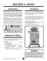
Page 17: ...cluded for the setup assembly of this machine Description Qty Hex Wrench 8mm 1 Additional People 1 Safety Glasses 1 Cleaner Degreaser Page 12 As Needed Disposable Shop Rags As Needed Forklift 1 Lifting Strap Rated for at least 750 lbs 2 Needed for Setup Inventory The following is a list of items shipped with your machine Before beginning setup lay these items out and inventory them If any non prop...

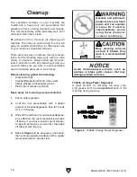
Page 18: ...aper optional Basic steps for removing rust preventative 1 Put on safety glasses 2 Coat the rust preventative with a liberal amount of cleaner degreaser then let it soak for 5 10 minutes 3 Wipe off the surfaces If your cleaner degreas er is effective the rust preventative will wipe off easily If you have a plastic paint scraper scrape off as much as you can first then wipe off the rest with the ra...

Page 19: ... described in this manual See below for required space allocation Physical Environment The physical environment where the machine is operated is important for safe operation and lon gevity of machine components For best results operate this machine in a dry environment that is free from excessive moisture hazardous chemi cals airborne abrasives or extreme conditions Extreme conditions for this typ...

Page 20: ...mbly The Model G0792 comes with the headstock in the horizontal position To safely lift the machine you must first adjust the headstock to the vertical position and install the upper roller crank handle To assemble machine 1 Use an 8mm hex wrench to remove two cap screws that secure headstock in horizontal position see Figure 7 Figure 7 Location of cap screws that secure headstock in horizontal po...

Page 21: ... you choose not to do this with your machine we rec ommend placing it on machine mounts as these provide an easy method for leveling and they have vibration absorbing pads Lag shield anchors with lag screws see below are a popular way to anchor machinery to a con crete floor because the anchors sit flush with the floor surface making it easy to unbolt and move the machine later if needed However a...

Page 22: ...ately disconnect power to machine Emergency Stop RESET but ton safety feature is not working correctly This safety feature must work properly before proceeding with regular operations Call Tech Support for help 4 Twist both Emergency Stop RESET buttons clockwise until they pop out this resets switches so they will allow power to machine Once assembly is complete test run the machine to ensure it i...

Page 23: ...machine operator with a basic understanding of how the machine is used during operation so the machine controls components discussed later in this manual are easier to understand Due to the generic nature of this overview it is not intended to be an instructional guide To learn more about specific operations read this entire manual and seek additional training from expe rienced machine operators a...

Page 24: ...ce as shown in Figure 14 then con nect machine to power 4 Tighten crank handle an additional 1 4 1 2 turn Note The amount of additional tightening varies depending on the strength of your workpiece material Therefore it is a good idea to first perform a test bend on a piece of scrap material to get a feel for how much force to exert when tightening 5 Use foot pedal controls see Figure 15 to move w...

Page 25: ...eeded Qty Hex Wrench 8mm 1 Figure 19 Headstock tilted to horizontal position for bending long arcs 2 Remove two cap screws shown in Figure 20 Figure 20 Location of cap screws that secure headstock in vertical position Cap Screws To position headstock in horizontal position 1 DISCONNECT MACHINE FROM POWER 6 When you reach end of your bend release foot pedal to stop motor 7 To increase bend create a...

Page 26: ...ffered by Grizzly see Page 22 for more information To roll a compound arc you must introduce a slight twist to the arc so that it bends in both axes This is accomplished by adjusting one of the guide rollers see Figure 22 so that it exerts lateral force on the workpiece as it passes through the headstock Depending on your workpiece material and desired results the following operation may require s...

Page 27: ...periment with a combination of adjustments to get the results you want This includes rotating the lower adjustment bolt see Figure 23 Upper Adjustment Bolt Lower Adjustment Bolt Workpiece Bent Laterally by Guide Roller Retaining Nut Figure 23 Location of compound bending components side view 2 Loosen upper guide retaining nut on outgoing side of headstock see Figure 23 3 Rotate upper guide adjustm...

Page 28: ... shape bends Max ID 3 Min ID 3 4 Fully adjustable Shipping weight is approx 53 lbs Figure 25 Model G7153 Universal Bender Round Material Dies Expand your bending capability with these round material dies from Grizzly allowing you to bend round stock for marine hand rails coils of tubing decorative iron work and much more T27631 1 2 Round T27632 3 4 Round T27633 1 Round SB1365 South Bend Way Oil IS...

Page 29: ... As Needed Grease NLGI 2 As Needed Lubrication Cleaning the Model G0792 is relatively easy Wipe down all unpainted and machined surfaces daily to keep them rust free and in top condition This includes any surface that is vulnerable to rust if left unprotected Use ISO 68 way oil or any other quality metal lubricant see Page 22 for offerings from Grizzly to prevent corrosion Cleaning Protecting To a...

Page 30: ... lubricate all gears at that time Leadscrew Oil Type Grizzly T23962 or ISO 68 Equivalent Oil Amount As Needed Lubrication Frequency As Needed Before lubricating the leadscrew see Figure 29 clean it first with mineral spirits A stiff brush works well to help clean out the threads Make sure to raise and lower the upper roller so you can clean the entire length of the leadscrew Figure 29 Leadscrew an...

Page 31: ...disconnected or corroded wires 9 Test replace 10 Test replace switch es 11 Test replace 12 Adjust replace centrifugal switch if available 13 Test repair replace Machine stalls or is underpowered 1 Machine undersized for task 2 Wrong workpiece material 3 Motor overheated 4 Motor wired incorrectly 5 Contactor not energized has poor contacts 6 Plug receptacle at fault 7 Gearbox at fault 8 Run capacit...

Page 32: ...le with workpiece shape 1 Reduce bending pressure of upper roller 2 Use workpiece suitable for bending operation use correct rollers for shape of workpiece Workpiece does not move when rollers rotate 1 Not enough bending pressure 2 Grease oil on workpiece rollers causing rollers to slip against workpiece 1 Increase bending pressure of upper roller 2 Thoroughly clean workpiece rollers to prevent sl...

Page 33: ...nt at the time of printing but may not match your machine If you find this to be the case use the wiring diagram inside the motor junction box CAPACITORS INVERTERS Some capacitors and power inverters store an electrical charge for up to 10 minutes after being disconnected from the power source To reduce the risk of being shocked wait at least this long before working on capacitors EXPERIENCING DIF...

Page 34: ...utton and forward facing controls Figure 31 Foot pedal wiring Emergency Stop Button Foot Pedal Controls Emergency Stop Button Master Power Switch Power Button Relay Transformer Contactor Terminal Figure 33 Motor junction box and starting switch 28 Model G0792 Mfd Since 12 15 READ ELECTRICAL SAFETY ON PAGE 27 ...

Page 35: ...O 6T3 4T2 2T1 1L1 22E SIEMENS 3TB41 24V KM2 3L2 5L3 43NO 31NC 21NC 13NO 14NO 22NC 32NC 44NO 6T3 4T2 2T1 QF3 CHNT CHNT QF1 QF2 DZ47 60 DZ47 60 D10 C3 PE L2 3 4 6 7 L1 PE E STOP Button 1NC Master POWER Switch E E LW8GS 25 30000 A PE PE 3 3 R1 S1 4 4 4 6 6 1U1 1U1 1U1 1U1 1U1 1V1 1V1 1V1 11 11 8 8 1 1 7 7 10 10 L1 L1 L2 L2 T1 T2 T3 L1 L2 L3 1L1 1L2 1L1 1L2 1L2 1L1 2L1 2L2 2L2 2L1 0 0 0 R1 S1 PE Anive...

Page 36: ...3 4 ZB2 BE102 Ground PE GND Foot Pedal Controls E Stop Button 6 6 10 7 PE 220V Motor Start Capacitor CD60 400MFD 275VAC 8 9 7 8 Run Capacitor CBB60 40MFD 450VAC ESS1 40 Starting Switch 4 4 3 3 2 2 1 1 5 4 4 1 1 5 To Control Panel Page 29 To Control Panel Page 29 Foot Pedal E Stop Diagram ...

Page 37: ...6 1 3 2 100 6 71 71 69 69 69 68 68 68 74 74 74 74 73 73 73 73 70 70 72 72 72 72 5 66 66 19 19 19 79 77 14 14 62 61 67 60 9 78V2 7 10 21 23 53 81 52 76 4 83 82 4 39 2V2 39 3 39 4 39 5 39 5 39 6 39 7 39 9V2 39 12 39 13 39 8V2 39 10 84 85 86 95 95 104 Main SECTION 9 PARTS We do our best to stock replacement parts when possible but we cannot guarantee that all parts shown are available for purchase Ca...

Page 38: ...AR 33T 74 P0792074 SET SCREW M8 1 25 X 20 DOG PT 30 P0792030 BUSHING 75 P0792075 CAP SCREW M8 1 25 X 30 31 P0792031 GEAR 68T 76 P0792076 DRIVESHAFT COVER 32 P0792032 GEAR 24T 77 P0792077 CAP SCREW M5 8 X 10 33 P0792033 GEAR 55T 78V2 P0792078V2 UPPER ROLLER PLATE W SCALE V2 12 15 34 P0792034 KEY 8 X 8 X 56 79 P0792079 FLAT WASHER 5MM 35 P0792035 EXT TOOTH LOCK WASHER 30MM 81 P0792081 VERTICAL SLIDE...

Page 39: ...BREAKER 3A CHNT DZ47 60 C3 1P 202 P0792202 ELECTRICAL PANEL MOUNTING PLATE 214 P0792214 FOOT SWITCH CORD 12G 6W 60 203 P0792203 WIRE RACEWAY 215 P0792215 POWER CORD 12G 3W 72 204 P0792204 POWER SWITCH E E LW8GS 25 30000 216 P0792216 MOTOR CORD 12G 5W 48 205 P0792205 DIN RAIL UPPER 217 P0792217 DIN RAIL LOWER 206 P0792206 CIRCUIT BREAKER 10A CHNT DZ47 60 D10 2P 218 P0792218 TERMINAL BAR 8P 207 P079...

Page 40: ... or service CRUSHING AMPUTATION INJURY HAZARD Do not place hands between rollers during use G0792 Machine Labels B 1 14 15 Size 1 1 unless otherwise noted Labels MUST be made of chemical resistant material COPYRIGHT GRIZZLY INDUSTRIAL INC FOR GRIZZLY MACHINES ONLY DO NOT REPRODUCE OR CHANGE THIS ARTWORK COLOR CODES 35 x 32mm CAUTION PANTONE 109 C PANTONE 151 C or RAL 2005 WARNING 38 x 64mm 38 x 63...

Page 41: ... metalworker ____ 0 2 Years ____ 2 8 Years ____ 8 20 Years ____20 Years 6 How many of your machines or tools are Grizzly ____ 0 2 ____ 3 5 ____ 6 9 ____10 7 Do you think your machine represents a good value _____Yes _____No 8 Would you recommend Grizzly Industrial to a friend _____Yes _____No 9 Would you allow us to use your name as a reference for Grizzly customers in your area Note We never use ...

Page 42: ...D LINE FOLD ALONG DOTTED LINE GRIZZLY INDUSTRIAL INC P O BOX 2069 BELLINGHAM WA 98227 2069 Place Stamp Here Name_______________________________ Street_______________________________ City______________State______Zip______ Send a Grizzly Catalog to a friend ...

Page 43: ... shall be tried in the State of Washington County of Whatcom We shall in no event be liable for death injuries to persons or property or for incidental contingent special or consequential damages arising from the use of our products To take advantage of this warranty contact us by mail or phone and give us all the details We will then issue you a Return Number which must be clearly posted on the o...

Page 44: ......

Reviews: