background image

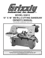
Model G0812 (Mfd. Since 2/16)

-9-

ELECTRICAL EQUIPMENT INJURY RISKS. 

You can be shocked, burned, or killed by touching 

live electrical components or improperly grounded 

machinery. To reduce this risk, only allow qualified 

service  personnel  to  do  electrical  installation  or 

repair work, and always disconnect power before 

accessing or exposing electrical equipment.

DISCONNECT POWER FIRST.  Always  discon-

nect  machine  from  power  supply  BEFORE  mak-

ing  adjustments,  changing  tooling,  or  servicing 

machine.  This  prevents  an  injury  risk  from  unin-

tended  startup  or  contact  with  live  electrical  com-

ponents.

EYE PROTECTION. Always wear ANSI-approved 

safety glasses or a face shield when operating or 

observing  machinery  to  reduce  the  risk  of  eye 

injury or blindness from flying particles. Everyday 

eyeglasses are NOT approved safety glasses.

OWNER’S MANUAL. Read and understand this 

owner’s manual BEFORE using machine. 

TRAINED OPERATORS ONLY. Untrained oper-

ators  have  a  higher  risk  of  being  hurt  or  killed. 

Only  allow  trained/supervised  people  to  use  this 

machine.  When  machine  is  not  being  used,  dis-

connect  power,  remove  switch  keys,  or  lock-out 

machine to prevent unauthorized use—especially 

around children. Make your workshop kid proof!

DANGEROUS ENVIRONMENTS. Do  not  use 

machinery in areas that are wet, cluttered, or have 

poor lighting. Operating machinery in these areas 

greatly increases the risk of accidents and injury.

MENTAL ALERTNESS REQUIRED. Full mental 

alertness is required for safe operation of machin-

ery. Never operate under the influence of drugs or 

alcohol, when tired, or when distracted.

For Your Own Safety, Read Instruction 

Manual Before Operating This Machine

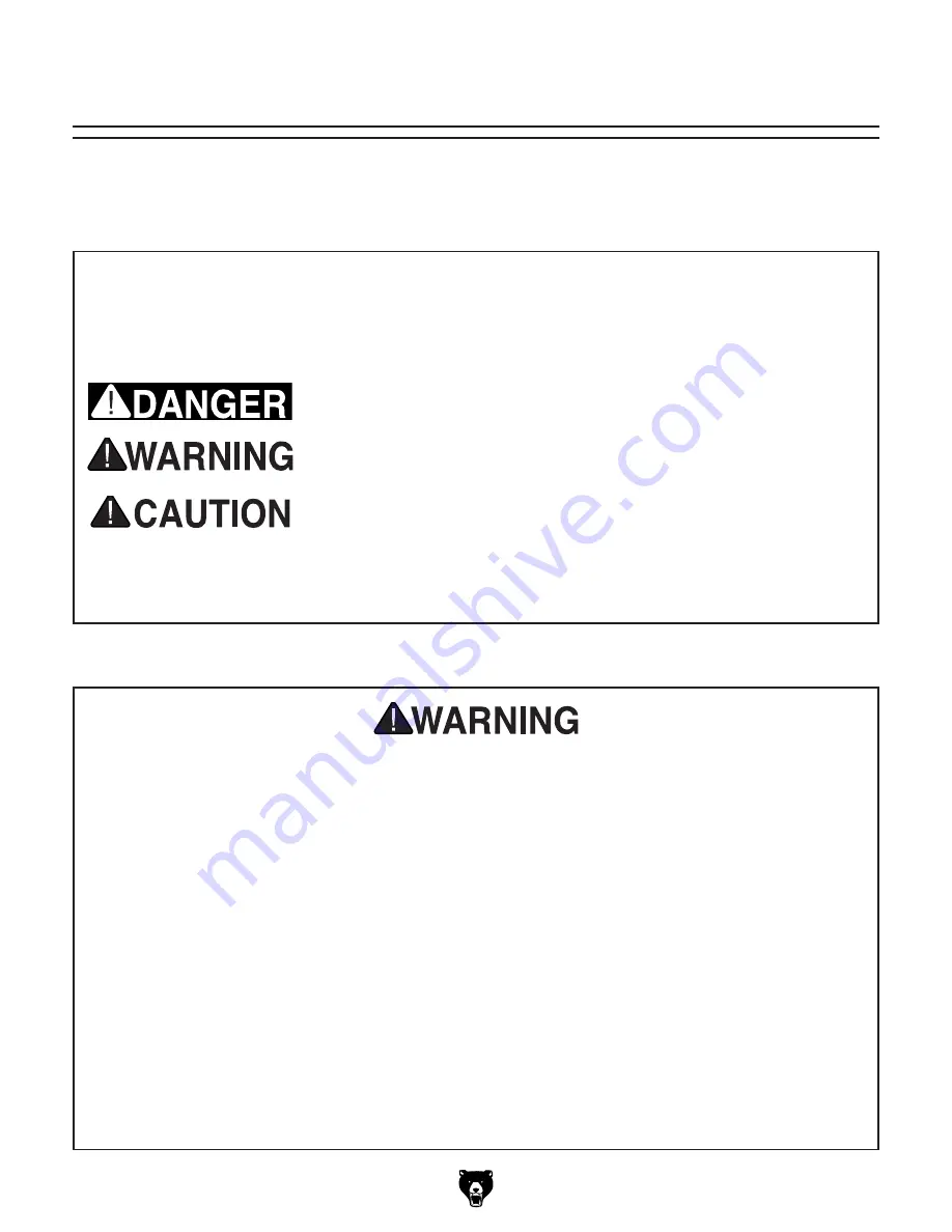
The purpose of safety symbols is to attract your attention to possible hazardous conditions. 

This manual uses a series of symbols and signal words intended to convey the level of impor-

tance of the safety messages. The progression of symbols is described below. Remember that 

safety messages by themselves do not eliminate danger and are not a substitute for proper 

accident prevention measures. Always use common sense and good judgment.

Indicates a potentially hazardous situation which, if not avoided, 
MAY result in minor or moderate injury. It may also be used to alert 
against unsafe practices.

Indicates a potentially hazardous situation which, if not avoided, 
COULD result in death or serious injury.

Indicates an imminently hazardous situation which, if not avoided, 
WILL result in death or serious injury.

Alerts the user to useful information about proper operation of the 
machine to avoid machine damage.

NOTICE

Safety Instructions for Machinery

SECTION 1: SAFETY

Summary of Contents for G0812

Page 1: ...NUAL For models manufactured since 2 16 COPYRIGHT JANUARY 2017 BY GRIZZLY INDUSTRIAL INC WARNING NO PORTION OF THIS MANUAL MAY BE REPRODUCED IN ANY SHAPE OR FORM WITHOUT THE WRITTEN APPROVAL OF GRIZZL...

Page 2: ...g grinding tool integrity and the usage of personal protective equipment The manufacturer will not be held liable for injury or property damage from negligence improper training machine modifications...

Page 3: ...op 32 Vise 34 Angle Cuts 36 Blade Guides 37 Coolant 38 Coolant System 38 Operation Tips 39 Workpiece Inspection 40 SECTION 5 ACCESSORIES 41 SECTION 6 MAINTENANCE 42 Schedule 42 Cleaning Protecting 42...

Page 4: ...de every effort to be exact with the instruc tions specifications drawings and photographs in this manual Sometimes we make mistakes but our policy of continuous improvement also means that sometimes...

Page 5: ...hown below to better understand the instructions in this manual Belt Cover Wheel Cover Blade Guide Knob Front View Headstock Blade Guide Scale Blade Guide Arm Work Stop Control Panel Hydraulic Tank Sp...

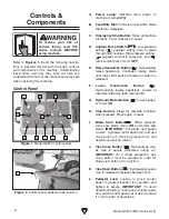
Page 6: ...et I Blade Start Button B A C D E F G H I J K L When pressed turns saw blade motor ON and starts saw blade IMPORTANT For blade start button to work hydraulic motor button G and vise close button J mus...

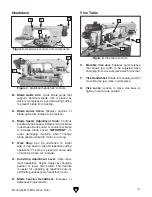
Page 7: ...cutting operations The stop is placed on same side of machine where cut is made Q Auto Stop Adjustment Lever Sets maxi mum headstock height Adjust by changing position of lower limit switch This featu...

Page 8: ...n Shipping Dimensions Type Wood Crate Content Machine Weight 1446 lbs Length x Width x Height 84 x 37 x 60 in Must Ship Upright Yes Electrical Power Requirement 220V Single Phase 60 Hz Prewired Voltag...

Page 9: ...ar Width at 90 Deg 18 in Max Capacity Round at 90 Deg 13 in Max Capacity Rectangular Height at 30 Deg 11 in Max Capacity Rectangular Width at 30 Deg 19 in Max Capacity Round at 30 Deg 19 in Max Capaci...

Page 10: ...roximate Assembly Setup Time 1 Hour Serial Number Location ID Label ISO 9001 Factory Yes Certified by a Nationally Recognized Testing Laboratory NRTL No Features Coolant System with 7 5 Gallon Coolant...

Page 11: ...proof DANGEROUS ENVIRONMENTS Do not use machinery in areas that are wet cluttered or have poor lighting Operating machinery in these areas greatly increases the risk of accidents and injury MENTAL AL...

Page 12: ...moving parts or flying debris Make sure they are properly installed undamaged and working correctly BEFORE operating machine FORCING MACHINERY Do not force machine It will do the job safer and better...

Page 13: ...ong cutting fluid could lead to chip fire and possible explosion CUTTING FLUID SAFETY Cutting fluids are poisonous Always follow manufacturer s cutting fluid safety instructions Pay particular attenti...

Page 14: ...y result especially if connected to an undersized circuit To reduce the risk of these hazards avoid over loading the machine during operation and make sure it is connected to a power supply circuit th...

Page 15: ...must be in good condition and contain a ground wire and matching plug receptacle Additionally it must meet the following size requirements Minimum Gauge Size 12 AWG Maximum Length Shorter is Better 5...

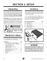
Page 16: ...ventory them If any non proprietary parts are missing e g a nut or a washer we will gladly replace them or for the sake of expediency replacements can be obtained at your local hardware store Box Inve...

Page 17: ...ore cleaning gather the following Disposable rags Cleaner degreaser WD 40 works well Safety glasses disposable gloves Plastic paint scraper optional Basic steps for removing rust preventative 1 Put on...

Page 18: ...low for required space allocation Physical Environment The physical environment where the machine is operated is important for safe operation and lon gevity of machine components For best results oper...

Page 19: ...djust each leveling hex bolt as needed to stabilize machine 8 Tighten hex nuts against frame to secure leveling bolts Figure 11 Leveling bolt threaded into frame 4 With an assistant helping to stabili...

Page 20: ...r if needed However anytime local codes apply you MUST follow the anchoring methodology specified by the code Machine Base Concrete Lag Screw Lag Shield Anchor Flat Washer Drilled Hole Figure 12 Popul...

Page 21: ...cut Refer to Work Stop on Page 32 for additional details 3 Slide work stop arm onto stop rod posi tion it as necessary then tighten cap screw see Figure 16 4 Insert work stop into arm and secure with...

Page 22: ...nd 3 the Emergency Stop button and lower limit switch work correctly Refer to Figure 18 during test run Each control has an alphabetical callout for identification DO NOT start machine until all prece...

Page 23: ...ency Stop button repeat Steps 12 13 then press Stop button B A C D E F G H I J K L H to stop machine 17 WITHOUT pressing Stop button again press hydraulic motor button B A C D E F G H I J K L G vise c...

Page 24: ...shipping we recom mend that you at least verify the following adjust ments to ensure accurate cutting results Step by step instructions on verifying these adjust ments can be found in SECTION 7 SERVIC...

Page 25: ...as close to workpiece as possible and verifies blade is properly tensioned 5 Makes sure workpiece and machine are stable and that there are no obstructions in the way of cut 6 Sets blade speed 7 Ensu...

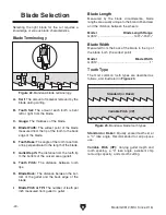
Page 26: ...and the back edge of the blade I Blade Pitch or TPI The number of teeth per inch measured from gullet to gullet Blade Selection Blade Terminology Figure 22 Bandsaw blade terminology G B C D E F H I A...

Page 27: ...d shape of material to be cut 4 In applicable row read across to right and find box where row and column intersect Listed in the box is minimum TPI recom mended for variable tooth pitch blades The TPI...

Page 28: ...struts lock into end of grooves on brackets shown in Figure 25 Figure 25 Wheel cover secured in up position 4 Loosen knob on left blade guide arm and move arm until it contacts stop pin on scale as s...

Page 29: ...section for details Figure 29 Blade installed on wheels Proper blade tension is essential to long blade life straight cuts and efficient cutting The Model G0812 features a blade tension indicator to a...

Page 30: ...s of blade breakage are avoidable The most common causes of avoidable blade breakage are Faulty alignment or adjustment of the blade guides Feeding blade through the workpiece too fast Dull or damaged...

Page 31: ...iding the warranty Use the Chip Inspection Chart on Page 31 as a guide to evaluate the chips and ensure that the optimal blade speed and feed rate are being used To properly break in new blade 1 Choos...

Page 32: ...de speed chart Material Speed FPM M Min Material Speed FPM M Min Material Speed FPM M Min Material Speed FPM M Min Carbon Steel 196 354 60 108 Tool Steel 203 62 Alloy Steel 111 321 34 98 Free Machinin...

Page 33: ...hard strong thin straight powdery thin curled tightly hard thin thin curled short hard thick thick hard strong thick hard strong thin straight powdery thin curled tightly hard thin thin curled short h...

Page 34: ...ench 4mm 1 Hex Wrench 6mm 1 Work Stop Setting Work Stop 1 Lower headstock completely 2 DISCONNECT MACHINE FROM POWER 3 Loosen set screws shown in Figures 37 38 Figure 38 Location of rear set screw for...

Page 35: ...workpiece then tighten cap screw and knob Repositioning Work Stop 1 To use work stop on opposite side of machine for straight or angle cuts see Figure 41 remove work stop arm from stop rod then remove...

Page 36: ...ht side for left angle cuts 5 Pull vise all the way to opposite side of base and tighten vise locks see Figure 44 6 Re install splash guard and work stop on side of vise base opposite of vise as shown...

Page 37: ...r push jaw in desired direction as required to accommodate workpiece 5 Insert workpiece between jaws and engage latch with leadscrew when vise is close to workpiece Use handwheel to move vise jaw unti...

Page 38: ...adstock positioned for cuts to right 6 Move saw through its full range of motion to make sure blade will not contact vise or control panel during operation then tighten swivel lock handle and secure v...

Page 39: ...s a wire brush that makes contact with the blade to help clear away chips and extend blade life see Figure 53 Figure 53 Blade brush Blade Brush Figure 52 Blade guides Right Blade Guide Left Blade Guid...

Page 40: ...dispose of coolant This bandsaw has a built in coolant system that can extend the life of your bandsaw blades by lowering the temperature of the blade and workpiece if used properly when cutting The c...

Page 41: ...ial firmly in the vise jaws to ensure a straight cut through the material Use vise close STAND BY START I OFF 1 2 3 4 5 6 7 8 9 0 HIGH LOW A E M H B C F I J K L G D STOP and vise open STAND BY START I...

Page 42: ...orkpieces Workpieces that can not be properly supported or stabilized with the vise should not be cut on this bandsaw Examples are chains cables workpieces with internal or built in moving or rotating...

Page 43: ...x 035 8 12 Variable Pitch T27649 150 x 1 x 035 10 14 Variable Pitch Figure 59 H9240 Rustlick Machining Oil H9240 Water Soluble Machining Oil Rustlick water soluble machining oil contains effective chl...

Page 44: ...cting Lubrication The bearings on your bandsaw are factory lubri cated and sealed Leave them alone unless they need to be replaced Always disconnect bandsaw from power before beginning any lubri catio...

Page 45: ...gs and a brush to clean the vise leadscrew from underneath the table When dry use a clean brush to apply a thin coat of oil or grease to the leadscrew threads see Figure 66 Blade Guides Lube Type Mode...

Page 46: ...arbox fill plug and sight glass Fill Plug 6 Replace drain plug remove drain pan then lower headstock to its lowest position 7 Fill gearbox with oil until oil level is at halfway point in sight glass t...

Page 47: ...exceed 140 F 60 C with an optimum operating temperature window of 50 95 F 10 35 C If the fluid temperature rises above 140 F stop the machine immediately and allow the fluid to cool down Figure 70 Fro...

Page 48: ...Re install tank lid and screen 12 Replace drain plug then fill tank approxi mately 80 percent full with 3 17 quarts of ISO 32 or equivalent hydraulic fluid 13 Re install tank fill cap and front access...

Page 49: ...in pulley grooves 5 Follow Steps 4 5 in Tensioning Belt proce dure to set correct belt tension 6 Re install belt cover so bracket aligns with slot see Figure 74 then re install variable speed covers...

Page 50: ...E Personal Protective Equipment such as long sleeve waterproof gloves protective clothing splash resistant safety goggles and a NIOSH approved respirator Although most swarf from machining operations...

Page 51: ...nk 3 Remove drain plug see Figure 79 empty tank contents into drain pan and dispose of fluid following federal state and fluid manu facturer requirements Changing Coolant 4 Thoroughly clean tank pump...

Page 52: ...s Needed Bringing Machine Out of Storage 1 DISCONNECT MACHINE FROM POWER 2 Remove moisture absorbing desiccant packs from electrical box 3 Re tension blade as described on Page 27 4 Repeat Test Run on...

Page 53: ...age and circuit size 8 Ensure circuit is sized correctly and free of shorts Reset circuit breaker or replace fuse 9 Correct motor wiring connections 10 Check fix broken disconnected or corroded wires...

Page 54: ...ncorrectly 2 Blade not square to table 1 Adjust angle stops Page 58 2 Adjust blade square to table Page 56 Blade dulls prematurely or metal sticking to the blade 1 Blade improperly broken in 2 Blade g...

Page 55: ...lve solenoids are faulty 2 Vise valve solenoids connections are bad 3 Vise hydraulic system is leaking 4 Control panel wiring is faulty 1 Test repair replace 2 Check solenoid plugs 3 Test for leaks re...

Page 56: ...l G0812 has an adjustable stop bolt to help support the headstock at the bottom of its travel If the blade does not travel far enough to complete the cut or hits the table this bolt will have to be ad...

Page 57: ...ngers 4 Tighten set screws 5 Adjust carbide blade guides see Figure 83 so they make same contact with blade as guide bearings 6 Adjust blade guide bearings on right blade guide assembly in same manner...

Page 58: ...fferent points along length of table between blade guide assemblies Figure 84 Checking blade to table squareness 4 Re tighten cap screws loosened earlier 5 Repeat Step 3 and adjustments above as neces...

Page 59: ...r blade type refer to Tensioning Tracking Blade on Page 27 3 Loosen screws that secure blade tension limit switch see Figure 86 and slide switch bot tom so it just touches switch plate 4 Start hydraul...

Page 60: ...88 Upper limit switch and feed stop 1 of 2 Feed Stop Upper Limit Switch Roller Plunger Figure 90 Swivel lock handle location 4 While standing by motor rotate headstock to right approximately 5 rotate...

Page 61: ...hould be square to vise 8 Repeat Steps 6 7 as necessary then tighten jam nut against stop block see Figure 93 without turning stop bolt Setting 45 Right Angle Stop 1 Raise headstock to highest positio...

Page 62: ...3 Slide vise to right position and secure it Refer to Changing Vise Position on Page 34 4 Connect machine to power and lower head stock all the way until it stops moving Figure 96 60 left stop bolt an...

Page 63: ...at the time of printing but may not match your machine If you find this to be the case use the wiring diagram inside the motor junction box CAPACITORS INVERTERS Some capacitors and power inverters st...

Page 64: ...s 63 64 Control Panel Page 65 Limit Switch Page 68 Limit Switch Page 68 Limit Switch Page 68 Limit Switch Page 68 Main Motor Page 66 Hydraulic Pump Page 69 Coolant Pump Page 67 Component Locations Mai...

Page 65: ...Model G0812 Mfd Since 2 16 63 READ ELECTRICAL SAFETY ON PAGE 61 Electrical Panel Photo Figure 98 Electrical panel wiring...

Page 66: ...L1 I 0 Fuse Fuse Fuse 2 T1 4 T2 6 T3 COM WATER ON LS UP LS DN FOOT PUMP PUMP WATER MOTOR AUTO AUTO DOWN START STOP UP CLOSE OPEN DOWN UP CLOSE OPEN OV RF 0350 200801 0808 J95 0808 L13 L13 L11 L11 14...

Page 67: ...er OFF Button NHD CB 01 Vise Clamp Button NHD CB 01 Saw UP Button NHD CB 01 Saw DOWN Button NHD CB 01 Vise Release Button NHD CB 01 Start Button NHD CB 01 Power Lamp NHD NLD 22 E Stop Button KEDU HY57...

Page 68: ...Bk Bk Bk Bk Bk 2 1 3 Gn U1 V1 R T S Circuit Breaker Kuoyuh 88 Series 15A To Electrical Panel Pages 63 64 To Electrical Panel Pages 63 64 Figure 101 Main motor wiring Figure 103 Hydraulic pump wiring F...

Page 69: ...Since 2 16 67 READ ELECTRICAL SAFETY ON PAGE 61 Coolant Pump Wiring To Electrical Panel Pages 63 64 COOLANT PUMP 220V Ground Run Capacitor 3MFD 450VAC Bk Bk Bk Bk Bk Bk Bk Bk Gn Gn 2 3 Figure 104 Cool...

Page 70: ...witch Shinozaki AZD 1112 11 12 23 24 Figure 107 Blade cover limit switch wiring RIGH SIDE TOP UPPER LEFT LOWER LEFT 11 12 23 24 Limit Switch Shinozaki AZD 1112 11 11 12 12 23 23 24 24 Limit Switch Shi...

Page 71: ...agram SAW BOW RAM PUMP PRESSURE GAUGE SUCTION FILTER HYDRAULIC PUMP MOTOR HYDRAULIC FLUID RESERVOIR VISE JAW RAM FEED RATE CONTROL VALVE PRESSURE GAUGE HYDRAULIC MANIFOLD FILL CAP SOL A SOL A SOL B SO...

Page 72: ...47 48 49 50 51 52 53 54 55 56 57 58 59 60 61 62 63 64 65 66 67 68 69 70 71 72 73 74 75 76 77 78 79 10 11 33 33 1 33 10 33 2 33 3 33 4 33 4 33 5 33 6 33 7 33 8 33 9 19 SECTION 9 PARTS Please Note We do...

Page 73: ...0 29 P0812029 FLAT WASHER 6MM 75 P0812075 TENSION SCALE POINTER 30 P0812030 CAP SCREW M6 1 X 12 76 P0812076 LEADSCREW 31 P0812031 BLADE COVER 77 P0812077 SET SCREW M5 8 X 10 32 P0812032 CAP SCREW M6 1...

Page 74: ...39 104 140141 142 143 144 145 146 147 148 149 150 151 152 153 154 155 156 157 158 159 160 160 1 160 2 160 3 160 4 160 5 161 161 1 161 2 161 3 166 166 1 166 2 166 3 167 168 169 170 173 171 172 173 1 17...

Page 75: ...0812168 CROSS ROUND HEAD SCREW M5 X 10L 117 P0812117 GEAR BOX ASSEMBLY 169 P0812169 CARBIDE GUIDE 118 P0812118 DRIVE WHEEL 170 P0812170 HEX SOCKET HEAD SCREW M6 X 20L 119 P0812119 BLADE 27 X 0 9 X 381...

Page 76: ...272 273 274 275 276 277 278 279 280 281 282 283 284 285 286 308 309 310 311 312 313 314 315 316 317 318 319 320 321 322 323 324 325 326 327 328 329 330 331 332 333 334 335 336 337 338 339 340 341 342...

Page 77: ...20 283 P0812283 GREASE FITTING 1 8 NPT STRAIGHT 228 P0812228 LOCK WASHER 8MM 284 P0812284 TAPERED ROLLER BEARING 32007 230 P0812230 CAUTION LABEL 285 P0812285 PIVOT SHAFT NUT 231 P0812231 CAP SCREW M8...

Page 78: ...MOTOR BEARING TYPE 353 P0812353 COVER 316 P0812316 HYDRAULIC TUBING 1 4 W X 39 1 2 L 354 P0812354 CAP SCREW M5 8 X 12 317 P0812317 HYDRAULIC TUBING 1 4 W X 78 3 4 L 355 P0812355 FLAT WASHER 5MM 318 P0...

Page 79: ...HD CB 01 Saw UP Button NHD CB 01 Saw DOWN Button NHD CB 01 Vise Release Button NHD CB 01 Start Button NHD CB 01 Power Lamp NHD NLD 22 E Stop Button KEDU HY57B 1 2 3 4 1 2 3 4 3 4 3 4 3 4 3 4 X1 X2 3 4...

Page 80: ...or serious injury read manual BEFORE using machine To get a new manual call 800 523 4777 or go to www grizzly com WARNING WARNING EYE LUNG INJURY HAZARD Always wear safety glasses and a respirator whe...

Page 81: ...n a woodworker metalworker ____ 0 2 Years ____ 2 8 Years ____ 8 20 Years ____20 Years 6 How many of your machines or tools are Grizzly ____ 0 2 ____ 3 5 ____ 6 9 ____10 7 Do you think your machine rep...

Page 82: ...LINE FOLD ALONG DOTTED LINE GRIZZLY INDUSTRIAL INC P O BOX 2069 BELLINGHAM WA 98227 2069 Place Stamp Here Name_______________________________ Street_______________________________ City______________S...

Page 83: ...shall be tried in the State of Washington County of Whatcom We shall in no event be liable for death injuries to persons or property or for incidental contingent special or consequential damages arisi...

Page 84: ......
Reviews: