-20-
Model G0812 (Mfd. Since 2/16)
Test Run
Once assembly is complete, test run the machine
to ensure it is properly connected to power and
safety components are functioning correctly.
If you find an unusual problem during the test run,
immediately stop the machine, disconnect it from
power, and fix the problem BEFORE operating the
machine again. The
Troubleshooting table in the
SERVICE section of this manual can help.
To test run machine:
1. Clear all setup tools away from machine.
2. Verify cutting fluid switch (
STAND BY
START
<< I
OFF
1
2
3
4
5
6
7
8
9
0
HIGH
LOW
A
E
M
H
B
C
F
I
J
K
L
G
D
STOP
, D) is OFF.
3. Fill coolant reservoir with coolant (refer to
Page 48), if you have not already done so.
DO NOT run pump without coolant or you will
damage it.
4. Connect machine to power source. Power
lamp (
B
A
C
D
E
F
G
H
I
J
K
L
, A) will illuminate.
5. Push Emergency Stop button (
B
A
C
D
E
F
G
H
I
J
K
L
, C) in, then
twist it clockwise so it pops out. When STOP
button pops out, switch is reset, and machine
is ready for operation (see
Figure 19).
The test run consists of verifying the following:
1) The hydraulic controls work correctly, 2) the
motor powers up and runs correctly, and 3) the
Emergency Stop button and lower limit switch
work correctly.
Refer to
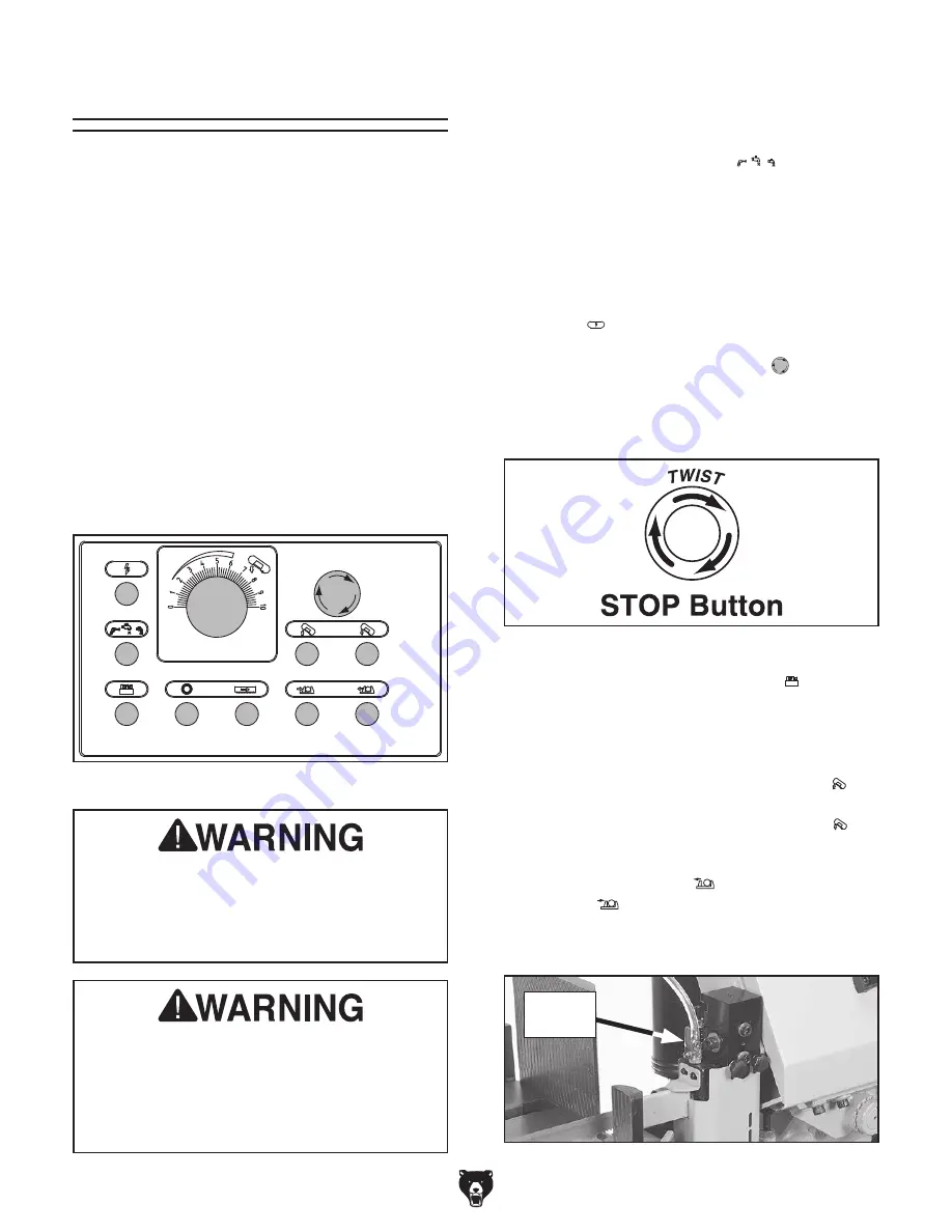
Figure 18 during test run. Each control
has an alphabetical callout for identification.
DO NOT start machine until all preceding
setup instructions have been performed.
Operating an improperly set up machine
may result in malfunction or unexpect-
ed results that can lead to serious injury,
death, or machine/property damage.
Serious injury or death can result from
using this machine BEFORE understanding
its controls and related safety information.
DO NOT operate, or allow others to operate,
machine until the information is understood.
A
D
G
H
I
J
K
E
F
C
B
Figure 18. G0812 Control panel.
Figure 19. Resetting the switch.
6. Press hydraulic motor button (
B
A
C
D
E
F
G
H
I
J
K
L
, G). You
should hear hydraulic motor (located in
machine base) turn
ON.
7. Check function of saw headstock hydraulics
by pressing raise headstock button (
B
A
C
D
E
F
G
H
I
J
K
L
, E)
setting feed dial (B) at a number over "0",
then pressing lower headstock button (
B
A
C
D
E
F
G
H
I
J
K
L
, F).
8. Check function of vise hydraulics by pressing
vise open button (
STAND BY
START
<< I
OFF
1
2
3
4
5
6
7
8
9
0
HIGH
LOW
A
E
M
H
B
C
F
I
J
K
L
G
D
STOP
, K) and vise close
button (
STAND BY
START
<< I
OFF
1
2
3
4
5
6
7
8
9
0
HIGH
LOW
A
E
M
H
B
C
F
I
J
K
L
G
D
STOP
, J).
9. Open coolant valves (see Figure 20).
Figure 20. Coolant valve (1 of 2) opened.
Coolant
Valve
Summary of Contents for G0812
Page 84: ......


