Model G0815 (Mfd. Since 09/18)
-43-
Positioning Chip
Deflector
Chip Deflector Gap Setting .....................
1
⁄
16
"–
1
⁄
8
"
When properly distanced from the cutterhead, the
chip deflector directs the chips into the dust hood,
and keeps them from falling onto the outfeed roller
and being pressed into the workpiece.
Tools Needed
Qty
Phillips Screwdriver #2 ...................................... 1
Hex Wrench 5mm .............................................. 1
Open-End Wrench or Socket 10mm ................. 1
Fine Ruler or Calipers ....................................... 1
To adjust chip deflector gap:
1. DISCONNECT MACHINE FROM POWER!
2. Remove dust hood, top cover, and belt
covers.
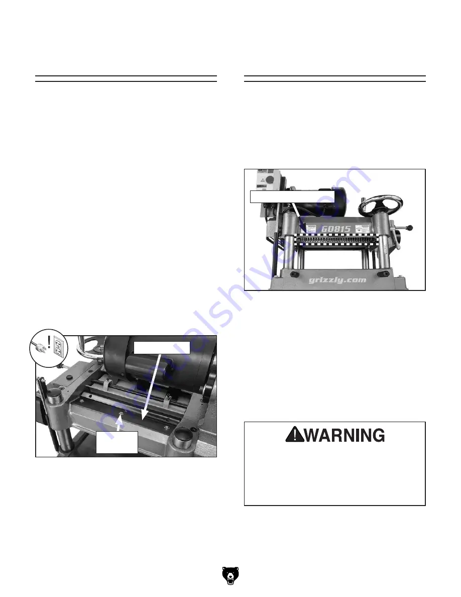
3. Use cutterhead pulley to rotate cutterhead
until a knife reaches closest distance to chip
deflector (see
Figure 59), then measure dis-
tance between knife and chip deflector.
Anti-Kickback
Fingers
The anti-kickback fingers are an important safety
feature of your planer. The fingers hang from a rod
suspended across the head casting and in front
of the infeed roller, as shown in
Figure 60. This
design allows the workpiece to easily enter the
planer but reduces the risk of kickback by digging
into the workpiece if it moves backward.
Figure 60. Anti-kickback fingers.
Anti-Kickback Fingers
Check the anti-kickback fingers regularly to ensure
they swing freely and easily. If the fingers do not
swing freely and easily, first clean them with a
wood resin solvent, then inspect them for dam-
age. If any of the fingers are damaged, the device
must be replaced before using the machine.
Do not apply oil or other lubricants to the anti-
kickback fingers that will attract dust and restrict
free movement of the fingers.
Proper operation of anti-kickback fingers
is critical for safe operation of this planer.
DO NOT operate planer if anti-kickback
fingers are not operating correctly. Failure
to heed this warning could result in serious
personal injury.
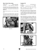
Figure 59. Chip deflector and securing flange
bolts.
Chip Deflector
4. If distance measured in Step 3 is not
1
⁄
16
"–
1
⁄
8
",
then loosen flange screws that secure chip
deflector and adjust gap to
1
⁄
16
"–
1
⁄
8
".
5. Retighten flange screws, then replace belt
covers, top cover, and dust hood.
Hex Bolts
(1 of 3)
Summary of Contents for G0815
Page 56: ......

