-36-
Model G0817 (Mfd. Since 05/16)
Aligning Table
To ensure cutting accuracy, the table should be
aligned so that the miter slot is parallel to the
bandsaw blade, and that the table is perpendicu-
lar (front to back) to the blade. These procedures
work best with a wide (
3
⁄
4
") blade installed.
Tools Needed
Qty
Straightedge ...................................................... 1
Fine Ruler .......................................................... 1
Square ............................................................... 1
Wrench or Socket 13mm ................................... 1
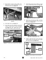
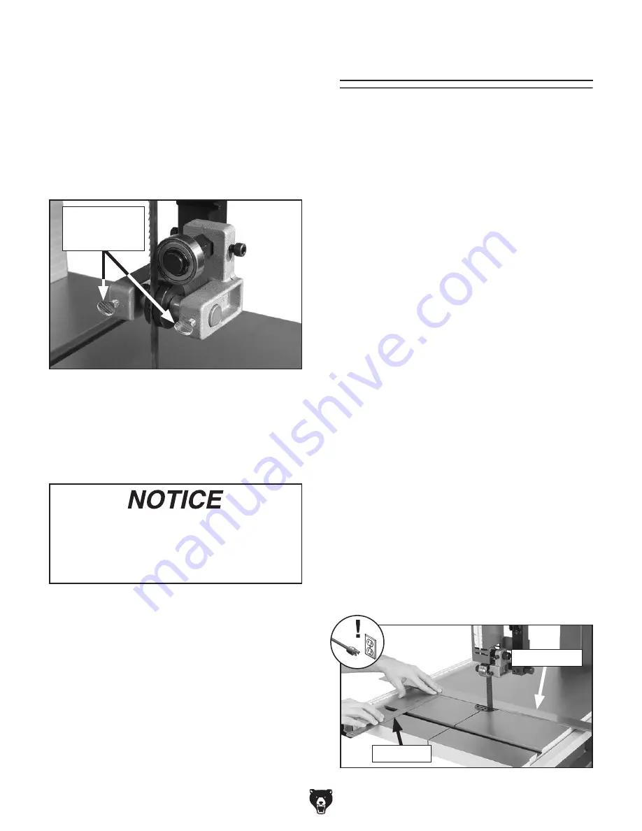
Figure 59. Checking miter slot parallelism.
Straightedge
Fine Ruler
Adjusting Miter Slot Parallelism
1. Make sure blade is tracking properly
and that it is correctly tensioned (refer to
Pages 25 & 28).
2. DISCONNECT MACHINE FROM POWER!
3. Place an accurate straightedge along blade
so that it lightly touches both front and back
of blade without going across a tooth (see
Figure 59).
4. Use a fine ruler to measure distance between
straightedge and miter slot (see
Figure 59).
Distance should be the same at front and
back of table.
— If the distance is the same at the front
and back of the table, no adjustment is
necessary; proceed to
Adjusting Table
Perpendicular to Blade on Page 37.
— If the distance is not the same at the front
and back of the table, it must be adjusted;
proceed to
Step 5.
3. Loosen both roller-disc adjustment thumb
screws (see
Figure 58), then position roller-
discs so they are close to —but not quite
touching—sides of blade.
Note: When the roller-discs are properly
adjusted, they should only contact the blade
during cutting operations, or when the blade
is deflected to the left or right. The discs may
or may not rotate during operations.
Whenever changing blade or adjusting
blade tension or tracking, the roller-discs
and support bearings must be re-adjusted
before resuming operation to ensure proper
blade support.
4. Retighten thumb screws to secure settings.
Rotate blade by hand to check setting, and if
necessary, repeat
Steps 3–4.
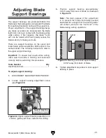
Figure 58. Location of upper roller-disc
adjustment thumb screws (guide post cover
removed for clarity).
Roller-Disc
Adjustment
Thumb Screws
Summary of Contents for G0817
Page 88: ......

