Model G0853 (Mfd. Since 07/18)
-33-
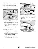
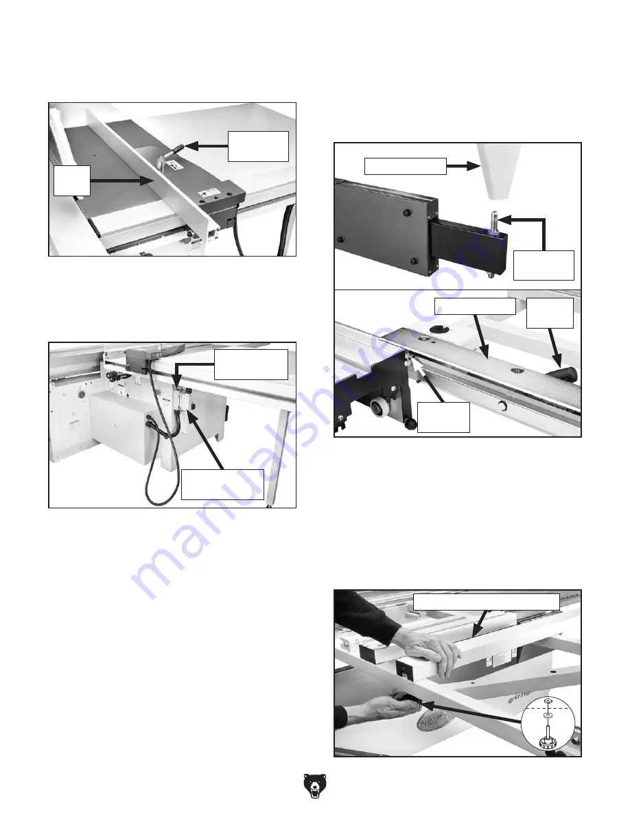
Figure 38. Rip fence wiring harness connector
attached to electrical box connector.
27. Attach rip fence wiring harness connector
(see
Figure 38) to electrical box connector
and lock both latches to secure.
26. Slide rip fence onto clamping plate, as shown
in
Figure 37, and secure with slide lock
handle.
Figure 37. Rip fence attached to rip fence base.
Slide Lock
Handle
Rip
Fence
Wiring Harness
Connector
Electrical Box
Connector
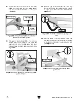
28. With assistance from other people, place
crosscut table on swing arm pivot pin and
place crosscut table mounting plate on sliding
table mounting rod, as shown in
Figure 39.
Tighten handle to lock crosscut table against
sliding table.
29. Slide (1) M8-1.25 T-nut into crosscut table
support bar T-slot, and align with hole in
crosscut table (see
Figure 40).
30. Secure support bar by threading (1) M8-1.25
x 50 knob bolt and 8mm fender washer into
T-nut (see
Figure 40).
Figure 39. Attaching crosscut table to machine
frame.
Crosscut Table
Swing Arm
Pivot Pin
Locking
Handle
Mounting Plate
Mounting
Rod
Figure 40. Attaching support bar to crosscut table.
Crosscut Table Support Bar
Summary of Contents for G0853
Page 24: ...22 Model G0853 Mfd Since 07 18 5mm Hardware Recognition Chart...
Page 140: ......


