-52-
Model G0853 (Mfd. Since 07/18)
The overhead control panel is capable of storing
the dimensions of up to ten different blades. This
information is critical when setting up the rip fence
to make precision cuts.
Adding/Deleting
Blade Dimensions
Adding Blade Dimensions
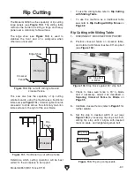
1. Press Tool-Box key on overhead control
panel (see
Figure 91).
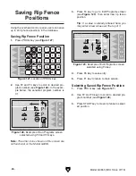
2. Use F2 and F3 keys to scroll up or down to
an open line (see
Figure 92).
Deleting Blade Dimensions
1. Press Tool-Box key on overhead control
panel (see
Figure 91).
2. Use F2 and F3 keys to scroll through list, and
stop on line to be deleted.
3. Press and hold F5 key for three seconds to
delete line.
4. Press F1 to return to main screen.
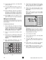
Figure 93. Tool-Box Edit screen.
4. Press F2 key, enter blade diameter, and
press F2 again to save.
5. Press F3 key, enter blade thickness, and
press F3 again to save.
Note: On machines manufactured before
June, 2021, blade dimensions can only be
entered in metric values. To upgrade to new
metric/standard computer chip, order PN
P08531655-1.
6. Press F5 key to save new dimensions to
database.
7. Press F1 key to return to main screen.
Blade Dimensions
Figure 91. Location of Tool-Box key.
F1
F2
F3
F4
F5
PROG.
CAL.
START
mm
inch
STOP
+
-
x
-
4
1
2
7
0
M+
CE
M-
3
6
5
8
9
F1
F2
F3
F4
F5
PROG.
CAL.
START
mm
inch
STOP
+
-
x
-
4
1
2
7
0
M+
CE
M-
3
6
5
8
9
Tool-Box
01
02
03
04
05
06
07
08
09
10
20.0mm
22.0
mm
26.0
mm
28.0
mm
3.2mm
3.6
mm
3.5
mm
3.8
mm
No
Figure 92. Tool-Box blade dimension screen.
3. Press F4 key to go to Tool-Box Edit screen
(see
Figure 93).
F1
F2
F3
F4
F5
PROG.
CAL.
START
mm
inch
STOP
+
-
x
-
4
1
2
7
0
M+
CE
M-
3
6
5
8
9
. 0
mm
300
Tool-Box Edit
No: 01
2 . 5
mm
1
Summary of Contents for G0853
Page 24: ...22 Model G0853 Mfd Since 07 18 5mm Hardware Recognition Chart...
Page 140: ......

