Model G0853 (Mfd. Since 07/18)
-63-
Making Grooves/Concealed Cuts
Based on blade width and workpiece dimensions,
the saw can be programmed to make a series of
cuts to create a groove. Refer to
Non-Through
Cuts on Page 47 for specific details on this type
of cut.
To make grooves/concealed cuts:
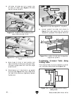
1. Press Tool-Box key (see Figure 120), and
use F2 or F3 keys to scroll to dimensions
for blade to be used in operation. If blade
dimensions have not been entered, enter
them now (refer to
Adding/Deleting Blade
Dimensions on Page 52).
F1
F2
F3
F4
F5
PROG.
CAL.
START
mm
inch
STOP
+
-
x
-
4
1
2
7
0
M+
CE
M-
3
6
5
8
9
. 0
mm
600
Grooving/
Concealed Cuts
10 . 0
mm
L
10 . 0
mm
3 . 2
mm
L
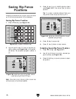
Figure 122. Grooving/Concealed Cuts screen.
5. Press F2 key and enter desired rip fence
starting position (see
Figure 122). This is
where the grooving cut will begin. Press
F2 key again to save entry.
6. Press F3 key and enter width of groove to be
cut (see
Figure 122). Press F3 key again to
save entry.
Note: Positive numbers move fence away
from blade; negative numbers move fence
toward blade.
7. Press F4 key and enter depth of groove to be
cut (see
Figure 122). Press F4 key again to
save entry.
IMPORTANT: Machine does NOT automati-
cally set blade height or tilt. This must be
done manually using blade controls on con-
trol panel. The purpose of entering groove
depth in this step is to ensure user has con-
sidered all variables before making a cut.
8. Confirm blade width shown on line F5 (see
Figure 122) matches dimension chosen in
Step 1. System will determine number of
cuts necessary to complete operation based
on this measurement.
Note: At this point, START key should be
illuminated, and number of cuts needed to
complete operation should be shown in lower
left-hand corner of screen.
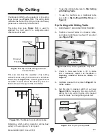
9. Press START key. Rip fence will move to
starting position.
10. Load workpiece onto table.
2. Press F1 to save selection and return to main
screen.
3. Ensure rip fence is calibrated for blade width
and fence face (narrow or wide) to be used in
operation (refer to
Calibrating Rip Fence on
Page 98).
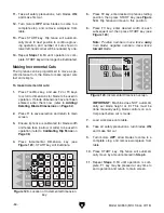
4. Press Grooving/Concealed Cuts key (see
Figure 121).
Figure 120. Location of Tool-Box key.
F1
F2
F3
F4
F5
PROG.
CAL.
START
mm
inch
STOP
+
-
x
-
4
1
2
7
0
M+
CE
M-
3
6
5
8
9
Figure 121. Location of Grooving/Concealed
Cuts key.
F1
F2
F3
F4
F5
PROG.
CAL.
START
mm
inch
STOP
+
-
x
-
4
1
2
7
0
M+
CE
M-
3
6
5
8
9
Making Grooves/Concealed Cuts
Summary of Contents for G0853
Page 24: ...22 Model G0853 Mfd Since 07 18 5mm Hardware Recognition Chart...
Page 140: ......


