background image

Model G0887 (Mfd. Since 01/19)

-49-

SECTION 6: MAINTENANCE

For optimum performance from this machine, this 
maintenance schedule must be strictly followed.

Ongoing
To minimize your risk of injury and maintain proper 
machine operation, shut down the machine imme-
diately if you ever observe any of the items below, 
and fix the problem before continuing operations:

• 

Loose mounting bolts.


Damaged or dull saw blade.


Worn or damaged wires.


Any other unsafe condition.

Daily Maintenance
• 

Lubricate blade and blade guides (

Page 51).

• 

Clean/lubricate table and vise (

Page 51).

Weekly Maintenance
• 

Lubricate headstock pivot points (

Page 52).

• 

Lubricate blade speed pulley (

Page 52).

• 

Lubricate vise shaft (

Page 52).

• 

Lubricate blade guide arm gib (

Page 52).

• 

Lubricate front wheel axle (

Page 52).

• 

Lubricate blade tension leadscrew (

Page 53).

Monthly Check
• 

Inspect drive belt (

Page 58).

Schedule

To reduce risk of shock or 

accidental startup, always 

disconnect machine from 

power before adjustments, 

maintenance, or service.

Cleaning & 

Protecting

Use  a  brush  and  shop  vacuum  to  remove  chips 
and other debris from the working surfaces.

Remove  any  rust  build-up  from  unpainted  cast 
iron  surfaces  of  your  machine  and  treat  with  a 
non-staining lubricant after cleaning.

Keep  unpainted  cast  iron  surfaces  rust-free  with 
regular  applications  of  products  like  G96

®

  Gun 

Treatment, SLIPIT

®

, or Boeshield

®

 T-9.

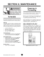
Figure 68. Boeshield® T-9 spray.

G2871—Boeshield

®

 T-9 12 Oz. Spray

G2870—Boeshield

®

 T-9 4 Oz. Spray

Perfect  for  unpainted  cast  iron  surfaces,  this 
ozone-friendly  protective  spray  penetrates  deep 
and  really  holds  up  against  corrosive  environ-
ments. Lubricates metals for months and is also 
safe for use on most paints, plastics, and vinyls. 
Developed by Boeing engineers for aircraft appli-
cations—this is the best!

Summary of Contents for G0887

Page 1: ...RTION OF THIS MANUAL MAY BE REPRODUCED IN ANY SHAPE OR FORM WITHOUT THE WRITTEN APPROVAL OF GRIZZLY INDUSTRIAL INC CS20972 PRINTED IN TAIWAN V1 06 21 MODEL G0887 20 X 26 5 HP INDUSTRIAL METAL CUTTING...

Page 2: ...g grinding tool integrity and the usage of personal protective equipment The manufacturer will not be held liable for injury or property damage from negligence improper training machine modifications...

Page 3: ...1 Using Vise 42 Adjusting Support Vise Guide 44 Adjusting Work Stop 44 Using Coolant System 45 SECTION 5 ACCESSORIES 47 SECTION 6 MAINTENANCE 49 Schedule 49 Cleaning Protecting 49 Lubrication 50 Hydra...

Page 4: ...ade every effort to be exact with the instruc tions specifications drawings and photographs in this manual Sometimes we make mistakes but our policy of continuous improvement also means that sometimes...

Page 5: ...educe your risk of serious injury read this entire manual BEFORE using machine Rear View Front View Movable Vise Jaw Fixed Vise Jaw Blade Speed Dial Blade Speed Display Coolant Valve 1 of 3 Workpiece...

Page 6: ...e B Blade Guide Scale Displays position of left blade guide arm relative to workpiece C Blade Guide Arms Hold guides that support blade Adjust left arm as close to workpiece as possible to prevent bla...

Page 7: ...to edit maximum headstock height S Angle Control Button Enters angle entry mode to edit headstock angle T Coolant Pump Button Turns coolant pump ON and OFF U Motor Stop Button Turns all motors OFF V B...

Page 8: ...mensions Type Wood Crate Content Machine Weight 3960 lbs Length x Width x Height 120 x 55 x 79 in Must Ship Upright Yes Electrical Power Requirement 220V 3 Phase 60 Hz Full Load Current Rating 25A Min...

Page 9: ...Main Specifications Operation Info Blade Speeds 106 315 FPM Std Blade Length 232 in Blade Length Range 231 1 2 232 1 4 in Std Blade Width 1 1 2 in Cutting Capacities Cutting Height 20 in Angle Cuts 0...

Page 10: ...inish Epoxy Other Wheel Size 23 5 8 in Blade Guides Carbide Steel Ball Bearings Coolant Capacity 10 gal Hydraulic Capacity 30 qt Other Specifications Country of Origin Taiwan Warranty 1 Year Approxima...

Page 11: ...proof DANGEROUS ENVIRONMENTS Do not use machinery in areas that are wet cluttered or have poor lighting Operating machinery in these areas greatly increases the risk of accidents and injury MENTAL AL...

Page 12: ...moving parts or flying debris Make sure they are properly installed undamaged and working correctly BEFORE operating machine FORCING MACHINERY Do not force machine It will do the job safer and better...

Page 13: ...ong cutting fluid could lead to chip fire and possible explosion CUTTING FLUID SAFETY Cutting fluids are poisonous Always follow manufacturer s cutting fluid safety instructions Pay particular attenti...

Page 14: ...maintenance Always stop machine and disconnect power before relieving hydraulic pressure Verify hydraulic pressure is at 0 PSI before proceeding with maintenance PREVENTING LEAKS Always support and r...

Page 15: ...result especially if connected to an undersized circuit To reduce the risk of these hazards avoid over loading the machine during operation and make sure it is connected to a power supply circuit tha...

Page 16: ...grounded If you ever notice that a cord or plug is damaged or worn discon nect it from power and immediately replace it with a new one Serious injury could occur if you connect machine to power befor...

Page 17: ...t included for the setup assembly of this machine This is an extremely heavy machine Serious personal injury or death may occur if safe lifting and moving methods are not fol lowed To be safe you will...

Page 18: ...nd inventory them If any non proprietary parts are missing e g a nut or a washer we will gladly replace them or for the sake of expediency replacements can be obtained at your local hardware store Inv...

Page 19: ...Model G0887 Mfd Since 01 19 17 Hardware Recognition Chart USE THIS CHART TO MATCH UP HARDWARE DURING THE INVENTORY AND ASSEMBLY PROCESS 5mm 5mm Flat Head Cap Screw...

Page 20: ...ng gather the following Disposable rags Cleaner degreaser WD 40 works well Safety glasses disposable gloves Plastic paint scraper optional Basic steps for removing rust preventative 1 Put on safety gl...

Page 21: ...elow for required space allocation Physical Environment The physical environment where the machine is operated is important for safe operation and lon gevity of machine components For best results ope...

Page 22: ...unsure about your abili ties or maximum load ratings of your lifting equipment Figure 10 Machine secured to shipping pallet Lag Screw and Flat Washer 1 of 4 Machine Foot 1 of 4 To assemble machine 1...

Page 23: ...on base shaft Support Vise Guide Support Vise Base Shaft Figure 12 Foot pad installation components Hex Bolt Hex Nut Foot Pad 5 Install 1 M16 2 x 75 DOG PT hex bolt and M16 2 hex nut at each lag scre...

Page 24: ...ons If no instructions were included use wiring diagram on Page 81 Note About Extension Cords Using an incor rectly sized extension cord may decrease the life of electrical components on your machine...

Page 25: ...shooting on Page 60 before pro ceeding with Test Run Test Run Once assembly is complete test run the machine to ensure it is properly connected to power and safety components are functioning correctly...

Page 26: ...does not run smoothly dis connect machine from power and refer to Troubleshooting on Page 60 before proceeding with Test Run 15 Press Emergency Stop button A to stop machine Note Failure indicator Em...

Page 27: ...19 Figure 19 Blade cover secure screws 2 of 4 Note Failure indicator door safety light L will illuminate to indicate wheel cover is open and that it must be closed before operation can resume 25 Whil...

Page 28: ...formal training before beginning any proj ects Regardless of the content in this sec tion Grizzly Industrial will not be held liable for accidents caused by lack of training To complete a typical cut...

Page 29: ...w and help you get the maximum life out of your saw blades Tips for cutting Use the work stop to quickly and accurately cut multiple pieces of stock to the same length Clamp workpiece firmly in the vi...

Page 30: ...during cut ting avoid cutting these workpieces if possi ble If you must cut a small or thin workpiece attach it to or clamp it between larger scrap pieces that will both support the workpiece through...

Page 31: ...manufacturer To select correct blade pitch 1 Measure material thickness This measure ment is distance from where each tooth enters workpiece to where it exits workpiece 2 Refer to Material Width Diame...

Page 32: ...ca tion Maintain the appropriate feed rate and blade speed and pay attention to the chip characteris tics Refer to Blade Speed Chart on Page 32 and Chip Inspection Chart on Page 33 Keep your blades cl...

Page 33: ...e as necessary for optimum cutting performance refer to Chip Inspection Chart on Page 33 for details To set blade feed rate 1 Push hydraulic pump button to turn hydraulic pump ON 2 Push raise headstoc...

Page 34: ...ed chart Material Speed FPM M Min Material Speed FPM M Min Material Speed FPM M Min Material Speed FPM M Min Carbon Steel 196 354 60 108 Tool Steel 203 62 Alloy Steel 111 321 34 98 Free Machining Stai...

Page 35: ...Coiled Thin Silver Increase Decrease Check Blade Pitch Straight Thin Silver Good Increase Powdery Silver Decrease Increase Coiled Tight Thin Silver Good Decrease Check Blade Pitch Figure 27 Chip insp...

Page 36: ...Extension x 2 Changing Blade All saw blades are danger ous and may cause per sonal injury To reduce the risk of being injured wear leather gloves when handling and uncoiling saw blades Item s Needed...

Page 37: ...ce the same direction as blade travel see Figure 32 Some blades will have a directional arrow as a guide Figure 32 Example of blade cutting direction Blade Travel 10 Apply a light amount of tension to...

Page 38: ...on is essential to avoid blade vibration twist or slippage on the wheels A cor rectly tensioned blade provides long blade life straight cuts and efficient cutting The three major signs of incorrect bl...

Page 39: ...ts by keeping the blade from twisting and drifting off the cut line To adjust the left blade guide loosen the adjust able handle on the left blade guide arm see Figure 38 and slide the arm guide as cl...

Page 40: ...ade guard is as supported as possible Figure 41 Blade guard extension components Left Blade Guard Blade Guard Extension x 2 Figure 40 Wheel cover secure screw locations 2 of 4 To adjust blade guard ex...

Page 41: ...urn on hydraulic pump 4 Set headstock height see Setting Headstock Height on Page 40 5 Set headstock angle see Setting Headstock Angle on Page 41 Figure 42 Manual and automatic controls Performing an...

Page 42: ...se vise to secure workpiece see Using Vise on Page 42 I Emergency Stop Button Emergency Stop button is depressed Twist to reset Setting Headstock Height The height that the headstock will travel is co...

Page 43: ...e to the absolute value then use the joystick to swivel the headstock in either direction For example inputting 15 will allow the head stock to swivel 15 or 15 To set headstock angle 1 Enter manual mo...

Page 44: ...Headstock control section Headstock Digital Readout Input Light Angle Control Button Increase Button Decrease Button Headstock Angle Joystick To avoid serious injury always turn saw OFF and allow bla...

Page 45: ...s that open and close the movable vise can be adjusted using the control panel see Figure 50 Figure 50 Vise controls Vise Close Button Vise Open Button 2 Loosen vise position lock handle by turning ha...

Page 46: ...Figure 52 6 Tighten extension lock handle 7 Tighten fine adjustment handle until plate is secure against workpiece see Figure 52 Figure 52 Support vise guide adjustment controls Fine Adjustment Handl...

Page 47: ...y issues must be taken into account to mix and use the correct coolant Always follow all product warnings and specifications and contact the cut ting fluid manufacturer for unanswered questions Use th...

Page 48: ...control flow of cutting fluid see Figure 57 Using Coolant System Figure 57 Coolant valve 1 of 3 open Coolant Valve Note Too much flow at the fluid nozzle will make a mess and can make the work area u...

Page 49: ...d to protect neoprene seals Great for general purpose or heavy duty applications Can be used on all metals except titanium Figure 60 Typical variable pitch bi metal cutting blade Replacement Bi Metal...

Page 50: ...T20451 Kirova Clear Safety Glasses T20452 Kirova Anti Reflective S Glasses T20456 DAKURA Safety Glasses Figure 64 Assortment of basic eye protection T20502 T20503 T20452 T20451 T20456 order online at...

Page 51: ...ion leadscrew Page 53 Monthly Check Inspect drive belt Page 58 Schedule To reduce risk of shock or accidental startup always disconnect machine from power before adjustments maintenance or service Cle...

Page 52: ...p Rags As Needed Grease Gun 1 Stiff Brush 1 Clean Brush 1 Hex Wrench 4 5mm 1 Ea SB1365 South Bend Way Oil ISO 68 Engineered for the high pressure exerted on horizontal or vertical ways and slides Prot...

Page 53: ...ing location Pivot Pin Grease Fitting Blade Blade Guides Lube Type SB1365 or ISO 68 Equivalent Oil Amount 1 2 Drops Lubrication Frequency Daily Place one or two drops of light machine oil on blade and...

Page 54: ...lade speed pulley using grease fitting shown in Figure 76 Figure 76 Blade speed pulley grease fitting location Blade Speed Pulley Grease Fitting Vise Shaft Lube Type T26419 or NLGI 2 Equivalent Amount...

Page 55: ...d premature wear of moving parts hoses and valves If you have never maintained a hydraulic system before WE STRONGLY RECOMMEND that you read books get formal training or seek the help of a qualified h...

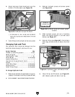
Page 56: ...Figure 84 and inspect for burnt smelling or tan colored water con taminated hydraulic fluid If fluid is contaminated proceed to Changing Hydraulic Fluid Figure 84 Hydraulic tank fluid gauge and fill c...

Page 57: ...6 Check fluid level Fluid should just cover the bottom of the fill screen see Figure 85 If fluid level is low slowly add hydraulic fluid until it just covers the bottom of the fill screen Changing Hy...

Page 58: ...re the swarf and metal chips are screened out and back into the reservoir Coolant System Maintenance Hazards As coolant ages and gets used dangerous microbes can proliferate and create a biological ha...

Page 59: ...Safety Wear See Hazards Coolant 10 Gallons Open End or Socket Wrench 17mm 1 Hex Wrench 4mm 1 10 Gallon Drain Pan 1 Clean Jug or Bucket 1 Water Hose w Spray Gun 1 Antibacterial Soap As Needed Disposabl...

Page 60: ...ve coolant pump access panel see Figure 92 5 Thoroughly clean reservoir and pump filter with hot soapy water then rinse with clean water You may need to remove coolant pump bracket screws to access pu...

Page 61: ...iccant packs inside of electrical box 6 Cover machine with tarp or plastic sheet that will keep out dust and resist moisture If machine will be near direct sunlight use cover that will block sun s ray...

Page 62: ...wiring 6 Close wheel cover replace switch 7 Tension blade correctly Page 36 replace switch 8 Ensure circuit is sized correctly and free of shorts Reset circuit breaker or replace fuse 9 Reset adjust t...

Page 63: ...or saw blade 5 Blade slipping on wheels 6 Belt slipping motor pulley slipping on shaft 7 Plug at fault wired incorrectly 8 Blade dull or installed backwards 9 Motor overheated 10 Contactor has poor co...

Page 64: ...acking Page 68 6 Verify blade has at least 3 teeth contacting material at all times Page 28 7 Clean wheels increase blade tension Page 36 8 Use applicable coolant lubricant Cuts not square 1 Blade not...

Page 65: ...pump motor is running and that solenoids are activating indicated by red LED in solenoid plug Repair replace if at fault 5 Test repair replace Symptom Possible Cause Possible Solution Blade wears on...

Page 66: ...nspect test for leaks repair 4 Make sure coolant line s are not pinched or damaged 5 Check that coolant pump motor is running Repair replace if at fault 6 Test repair replace Cooling system is pulling...

Page 67: ...s is con sidered a normal wear item and is not covered by warranty Item s Needed Qty Hex Wrench 4mm 1 To adjust blade brush 1 DISCONNECT MACHINE FROM POWER 2 Open wheel cover by removing 4 button head...

Page 68: ...Carbide Blade Guides The carbide blade guides and roller bearings come adjusted from the factory but due to blade changes shipping storage and time they may need adjustment Uneven blade wear and crook...

Page 69: ...ck off knob 1 2 turn DO NOT over tighten knobs Adjusting Roller Bearings Guide roller bearings should only be adjusted after the carbide blade guides see Adjusting Carbide Blade Guides on Page 66 To a...

Page 70: ...at the feed rate and blade speed are correct the blade is not dull and has correct teeth style and TPI for material the blade tension is correct and the blade is properly lubricated Items Needed Qty H...

Page 71: ...eps 6 7 as needed until back of blade lightly touches shoulder of idler wheel while tracking 9 Close wheel cover when proper blade track ing has been achieved Figure 104 Blade tracking properly agains...

Page 72: ...le surface 2 DISCONNECT MACHINE FROM POWER 3 Move left blade guide arm all the way left 4 Open wheel cover by removing 4 button head cap screws see Figure 106 You may need to move vise support for cle...

Page 73: ...s not start blade tension limit switch is working correctly and no adjust ment is required If motor does start proceed to Step 3 to adjust blade tension limit switch 3 DISCONNECT MACHINE FROM POWER 4...

Page 74: ...tart repeat Steps 4 8 until hydraulic motor does not start without cor rect blade tension Adjusting Downfeed Stop Bolt If the blade does not travel far enough to complete the cut or the blade contacts...

Page 75: ...g Headstock Spring The spring under the headstock that controls downward pressure of the headstock during cut ting operations should have the correct tension The tension should only be adjusted if ten...

Page 76: ...tinuing operation 3 Adjust blade speed dial to maximum speed setting 5 While an assistant holds motor loosen 4 motor hex bolts see Figure 118 Figure 116 Outer pulley cover and securing button head ca...

Page 77: ...y cover Tensioning Belt Drive belt should have a 1 4 of belt deflection To tension belt 1 DISCONNECT MACHINE FROM POWER 2 Remove 5 button head cap screws and flat washers to remove outer pulley cover...

Page 78: ...CS Hydraulic System Schematic Saw Bow Cylinder Vise Jaw Cylinder Pressure Gauge Pressure Check Valve Hydraulic Motor Hydraulic Pump Assembly Pressure Sensor Saw Bow Solenoid Valve Vise Jaw Solenoid Va...

Page 79: ...AULIC CYLINDER FEED RATE CONTROL VALVE FILL CAP PUMP SUCTION FILTER PUMP MOTOR PRESSURE GAUGE FLOW CONTROL VALVE PRESSURE GAUGE SOL A SOL A SOL B SOL B Directional Valve DSG 02 3C2 A2 N Directional Va...

Page 80: ...t at the time of printing but may not match your machine If you find this to be the case use the wiring diagram inside the motor junction box CAPACITORS INVERTERS Some capacitors and power inverters s...

Page 81: ...Potentiometer Page 85 3 Home Proximity Sensor Page 85 11 Table Motor Page 88 4 Coolant Pump Motor Page 87 12 Power Connection Page 81 5 Blade Brush Motor Page 87 13 Electrical Cabinet Page 81 82 6 Bla...

Page 82: ...oolant Pump Motor Home Proximity Sensor Table Motor Blade Motor Blade Speed Meter Blade Tension Limit Switch Control Panel 1 4 9 Electrical Cabinet 11 7 Hydraulic Unit 2 3 Blade Speed Sensor 6 8 Blade...

Page 83: ...TOR EV WATER EV PUMP EV OV EMER SW 12 Circuit Board RF500M 0904 TECO CU 18 13NO 21NC 22NC 14NO 1L1 3L2 5L3 13NO A1 2T1 4T2 6T3 14NO A2 Contactor NHD C 06D10 TEST 16 14 12 11 3 A TRIP IND 97 NO 98 NO 9...

Page 84: ...PUMP EV OV EMER SW 12 Circuit Board RF500M 0904 L4 L3 1 3 5 7 9 2 4 6 8 10 1 2 To Headstock Lower Limit Switch 3 4 To Door Safety Limit Switch 5 6 To Blade Tension Limit Switch To Hydraulic Unit 7 8 1...

Page 85: ...Model G0887 Mfd Since 01 19 83 READ ELECTRICAL SAFETY ON PAGE 78 Figure 122 Electrical cabinet components and wiring connections...

Page 86: ...m HYDRAULIC MANIFOLD 1 2 To Electrical Cabinet To Electrical Cabinet 2 1 2 1 2 1 To Electrical Cabinet 19 20 2 1 21 22 23 24 26 25 SOL A SOL A SOL B SOL B Directional Valve DSG 02 3C2 A2 N Directional...

Page 87: ...22 Key Switch NHD CB 10 NSS22 K 3 4 Auto Mode Button NHD CB 10 NHD PL BA9 NLB22 F 3 4 3 4 E Stop Button KEDU HY57B 1 2 Rotary Potentiometer Cosmos RV24YN 20S B103 18 L3 35 36 38 18G L4 LS UP LS DN GND...

Page 88: ...19 READ ELECTRICAL SAFETY ON PAGE 78 Figure 126 Control panel components and wiring connections Motor Wiring Diagrams Figure 127 Main motor junction box MAIN MOTOR 220V W2 U2 V2 U1 V1 W1 W V U To Ele...

Page 89: ...V1 Figure 129 Hydraulic unit motor junction box Figure 130 Coolant pump motor junction box COOLANT PUMP MOTOR 220V To Electrical Cabinet V2 W2 U2 1 2 3 4 5 6 Figure 128 Blade brush motor junction box...

Page 90: ...ANLIE AZD S11 11 12 23 24 5 6 To Electrical Cabinet Blade Tension Limit Switch SHINOZAKI AZD 1001T To Electrical Cabinet 11 12 23 24 7 8 Blade Tension Limit Switch Figure 133 Blade tension limit switc...

Page 91: ...switch Headstock Lower Limit Switch Headstock Lower Limit Switch CANLIE AZD 1001T To Electrical Cabinet 11 12 23 24 3 4 Figure 136 Blade speed sensor Figure 135 Blade speed meter Blade Speed Meter Bl...

Page 92: ...9 10 11 12 14 13 15 16 17 18 19 20 21 22 23 25 24 26 27 28 29 30 31 32 33 33 32 34 35 34 35 36 37 38 39 40 41 42 43 51 45 44 50 49 47 48 46 53 54 52 55 56 56 57 57 58 59 60 61 62 63 64 65 67 66 68 69...

Page 93: ...ED SHAFT 40 X 56 X 312 5 85 P0887085 PULLEY COVER INNER 30 P0887030 TENSION TRACKING SLIDE BLOCK 86 P0887086 FLAT WASHER 5MM 31 P0887031 SOLID PIN 16 X 90MM 87 P0887087 BUTTON HD CAP SCR M5 8 X 12 32...

Page 94: ...P0887133 FLAT WASHER 6MM 118 P0887118 BLADE BRUSH MOTOR BRACKET COVER 134 P0887134 WING BOLT M6 1 X 12 119 P0887119 FLAT WASHER 6MM 135 P0887135 BLADE BRUSH DRIP FLAP 120 P0887120 BUTTON HD CAP SCR M6...

Page 95: ...06 208 207 212 211 210 215 216 217 218 219 220 221 227 228 229 230 231 232 233 234 235 235 236 237 238 239 240 241 242 243 245 250 251 252 253 254 255 257 256 258 222 223 224 225 226 259 260 265 266 2...

Page 96: ...55 X 40 182 P0887182 LOCK WASHER 12MM 236 P0887236 VISE SHAFT 183 P0887183 CAP SCREW M12 1 75 X 35 237 P0887237 VISE HYDRAULIC CYLINDER 184 P0887184 TABLE WORM SHAFT 6T 238 P0887238 MOVABLE VISE JAW 1...

Page 97: ...HEADSTOCK SWIVEL BASE 335 P0887335 SENSOR BRACKET 301 P0887301 HEADSTOCK SWIVEL SHAFT 336 P0887336 FLAT WASHER 6MM 302 P0887302 TAPERED ROLLER BEARING 30312J 337 P0887337 CAP SCREW M6 1 X 10 303 P088...

Page 98: ...80 383 382 381 384 385 386 387 388 389 388 390 391 392 393 394 395 396 396 397 400 401 402 410 411 412 413 414 416 417 420 421 422 423 424 426 425 427 428 429 435 436 437 443 439 438 440 441 442 445 4...

Page 99: ...ROL PANEL ACCESS PANEL 385 P0887385 CHIP COLLECTION BIN 445 P0887445 FEED RATE CONTROL UNIT 386 P0887386 SPLASH GUARD FRONT 446 P0887446 PHLP HD SCR M5 8 X 10 387 P0887386 SPLASH GUARD REAR 447 P08874...

Page 100: ...13 OIL LEVEL GAUGE LS 3 470 3 P0887470 3 MOTOR JUNCTION BOX 470 14 P0887470 14 MANIFOLD ASSEMBLY HORIZONTAL 470 4 P0887470 4 BALL BEARING 6205ZZ FRONT 470 15 P0887470 15 PILOT CHECK VALVE MPC 02 W 30...

Page 101: ...X 20 540 P0887540 SUPPORT VISE BASE 514 P0887514 CARBIDE GUIDE MOUNTING BLOCK RIGHT 541 P0887541 SUPPORT VISE BASE LOCK COLLAR 515 P0887515 CAP SCREW M8 1 25 X 40 542 P0887542 ADJUSTABLE HANDLE M8 1...

Page 102: ...87608 3 WAY HOSE CONNECTOR 5 16PT BRASS 602 P0887602 T CONNECTOR 3 8PT 609 P0887609 COOLANT HOSE 5 16 X 2500MM 603 P0887603 HOSE FITTING 3 8PT X 5 16PT 610 P0887610 COOLANT HOSE 5 16 X 1800MM 604 P088...

Page 103: ...12 710 714 714 BLADE SPEED SENSOR METER Speed Sensor Yawfong DA1805PO 714 HOME PROXIMITY SWITCH 715 716 717 REF PART DESCRIPTION REF PART DESCRIPTION 701 P0887701 CIRCUIT BOARD RF500DSB 1312 709 P0887...

Page 104: ...GND LS CLIP GND LS DOWN GND SAFE SW GND BROKE SW GND AUTO STOP GND UB 1 GND UB 2 OV MOTOR EV WATER EV PUMP EV OV EMER SW 12 Circuit Board RF500M 0904 TECO CU 18 13NO 21NC 22NC 14NO 1L1 3L2 5L3 13NO A1...

Page 105: ...824 P0887824 FUSE 32A 250V CERAMIC 0 36 808 P0887808 POWER SWITCH ASSY ABB 0T25F3 YJ1 20 825 P0887825 VFD ABB ACS150 03E 04A7 2 809 P0887809 CONTACTOR NHD C 06D10 24V 826 P0887826 BRAKING RESISTOR 250...

Page 106: ...nattended EYE INJURY HAZARD Always wear safety glasses when using this machine DISCONNECT POWER BEFORE ADJUSTMENTS MAINTENANCE OR SERVICE READ and UNDERSTAND instruction manual to avoid serious injury...

Page 107: ...rty or for incidental contingent special or consequential damages arising from the use of our products The manufacturers reserve the right to change specifications at any time because they constantly...

Page 108: ......

Reviews: