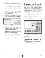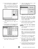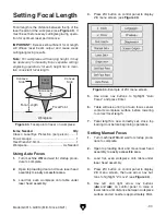
HEAVY LIFT!
Straining or crushing injury
may occur from improperly
lifting machine or some of
its parts. To reduce this
risk, use a forklift (or other
lifting equipment) rated for
weight of this machine.
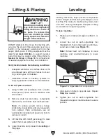
Figure 15. Adjustable foot components.
-22-
Model G0911–G0914 (Mfd. Since 05/21)
DO NOT attempt to lift or move this machine with-
out using the proper lifting equipment (such as a
forklift) or the necessary assistance from other
people. Each piece of lifting equipment must be
rated for
at least 2300 lbs. to support dynamic
loads that may be applied while lifting. Refer to
Needed for Setup on Page 18 for complete list
of needed equipment for setup and installation.
Verify location meets the following conditions:
•
Adequate ventilation so machine does not fill
an enclosed area with toxic fumes from cut-
ting certain types of materials.
•
Immediate access to auxiliary systems for
verifying operation and ease of maintenance.
To lift and place machine:
1. Using forklift and assistance from an addi-
tional person, move crate to machine work
site location.
2. Remove crate top and sides, components
inside crate, and blocks near machine base.
Note: To reduce weight, remove honey-
comb table, blade table, and any loose parts
from cabinet. Table components are not
permanently mounted and require no tools to
remove or install.
3. Lift machine with forklift just enough to clear
pallet, then move pallet out of the way.
4. Lower machine and proceed to Leveling on
this page.
Lifting & Placing
Leveling machinery helps precision components
remain straight and flat during the lifespan of the
machine. The table of a machine may slowly twist
over time, causing inadequate workpiece cutting
and variations in engraving quality.
To level machine:
1. Place level on table and align to either X- or
Y-axis.
2. Loosen hex nut on each adjustable foot
threaded bolt, then rotate fixed nut until mea-
sured axis is level (see
Figure 15).
Note: Rotate fixed nut clockwise to raise
machine, and counterclockwise to lower
machine.
Leveling
3. Align level on table to opposite axis. Repeat
Step 2 as needed.
4. Tighten hex nut on each adjustable foot
threaded bolt against machine base to secure
position.
Fixed Nut
Foot Pad
Hex Nut
Threaded
Bolt
Summary of Contents for G0911
Page 100: ......

