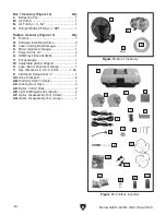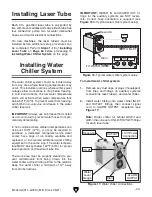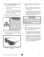
Figure 20. Air bubbles present in laser tube.
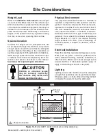
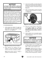
Figure 18. Water and air fittings for auxiliary
systems connections (G0911/G0912 shown).
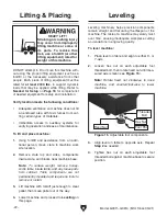
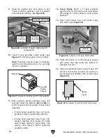
Figure 19. Water level gauge location.
-24-
Model G0911–G0914 (Mfd. Since 05/21)
3. Connect opposite end of OUTLET hose to
auxiliary systems WATER IN
fitting (see
Figure 18).
4. Connect opposite end of INLET hose to
auxiliary systems WATER OUT fitting (see
Figure 18).
5. Connect signal cord to SIGNAL receptacle on
machine (see
Figure 18).
6. Fill water chiller reservoir with 1
1
⁄
2
gallons of
distilled water.
IMPORTANT: The cooling system requires
distilled water to prevent scaling and con-
taminant build-up. Water quality and effective
cooling directly contribute to the operational
life of the laser tube.
7. Connect power cord to 110V power connec-
tion on water chiller (see
Figure 19).
8. Connect water chiller system to power and
turn
ON. Allow water to cycle for one minute
and continue filling reservoir with distilled
water until water level is in green area on
water level gauge (see
Figure 19).
Note: Water chiller can be connected to aux-
iliary power connection on rear of machine.
9. Open laser tube access door and verify large
air bubbles have released from laser tube
(see
Figure 20).
Note: If needed, loosen laser tube saddle
straps then slowly rotate laser tube while
slightly raising tube at cathode-end to release
persistent air bubbles.
Large Air
Bubbles
Water
Level
Gauge
110V Power
Connection
Summary of Contents for G0911
Page 100: ......

