

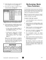


Before loading a workpiece, measure and
verify that sufficient space exists between
laser head tip and workpiece. Inadvertent
contact with laser head assembly during
workpiece loading can damage machine.
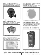
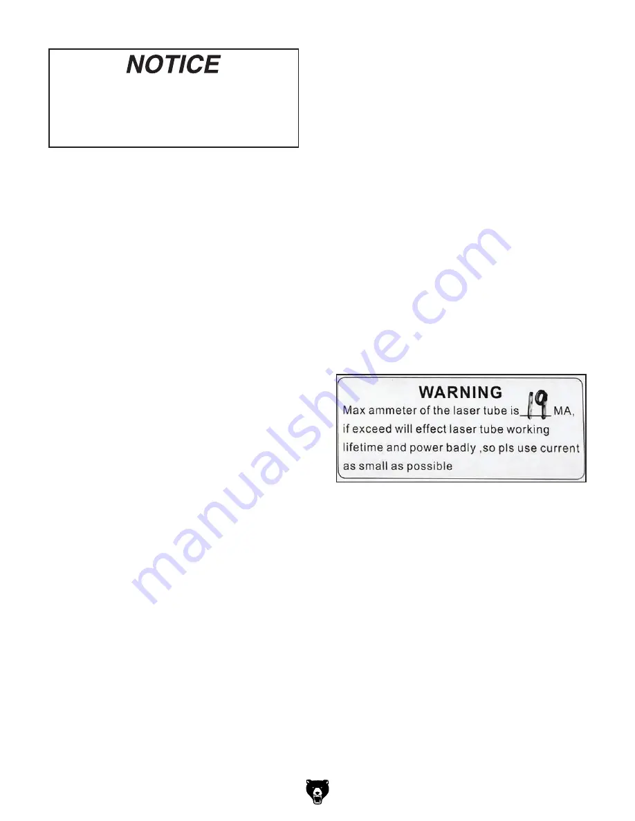
Figure 49. Example of ammeter mA rating.
Model G0911–G0914 (Mfd. Since 05/21)
-43-
13. Turn ON all auxiliary systems and verify
operation.
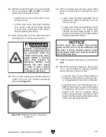
14. Put on Class 4 laser eye protection.
15. Close top loading door and press Start-Pause
button to begin laser operations.
Note: If problems arise, or job must be
stopped for a period of time, press Start-
Pause button to pause or resume operations.
In case of power interruption, or Emergency
Stop button is pressed, machine will resume
operations exactly where the event occurred
once power is restored.
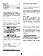
16. During operation, verify ammeter indicator
does not exceed mA rating listed above
ammeter (see
Figure 49).
IMPORTANT: An ammeter indication exceed-
ing mA rating may be caused by impending
laser tube failure, or electrical faults.
7. Measure thickness of workpiece and verify
adequate space exists between workpiece
and laser head assembly, then place
workpiece on table.
Note: Excess space will be adjusted later
when setting focal length.
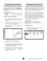
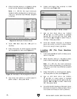
8. Load .RD file from machine memory (see
Loading .RD File From Machine Memory
on
Page 36).
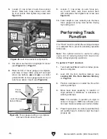
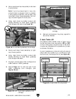
9. Use arrow nav buttons on control panel to
move laser head assembly to origin, then
push Origin button on control panel.
IMPORTANT: Controller requires laser head
assembly to be moved using arrow nav but-
tons to accurately determine position.
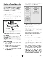
10. Set focal length as instructed in Setting
Focal Length on Page 37.
11. Perform "Track" function (see Performing
Track Function on Page 38).
12. Perform "Work time" function (see Performing
Work Time Function on Page 39).
17. When laser operations are completed, turn
machine
OFF.
18. Turn OFF all auxiliary systems.
19. Remove workpiece and scrap parts, put all
tools away, and clean area for next operation.
Summary of Contents for G0911
Page 100: ......


