

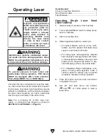


Operator and bystanders
MUST wear ANSI-approved
eye protection rated for
10,600 nm (10.6 µm) wave-
length CLASS 4 infrared
lasers when machine is
operating. NEVER look
directly into laser beam
or stare at laser contact
point, or severe eye injury
or blindness will occur!
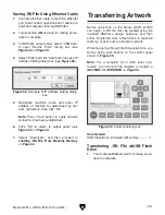
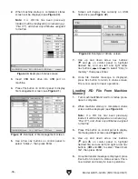
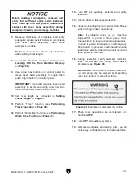
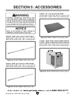
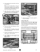
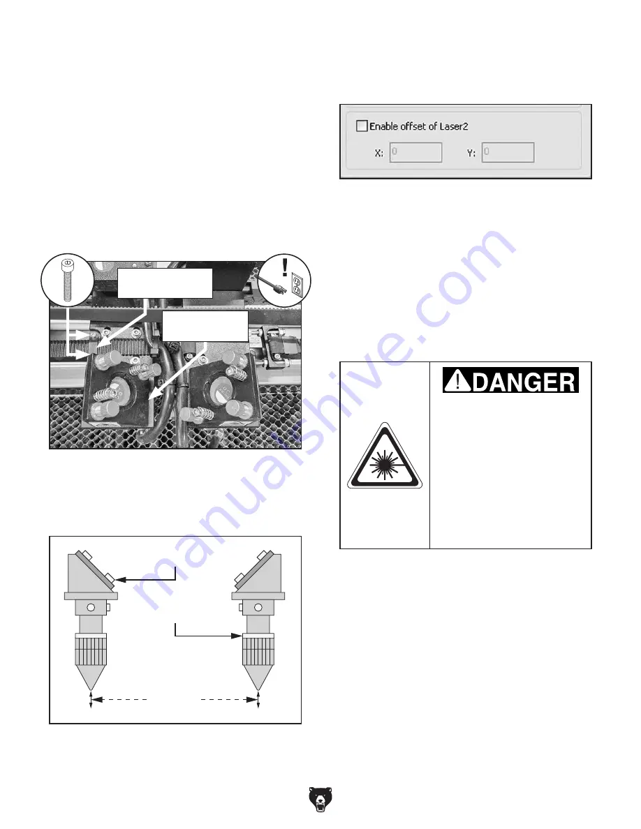
Figure 50. Left belt mounting bracket location.
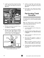
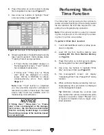
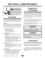
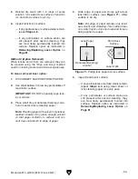
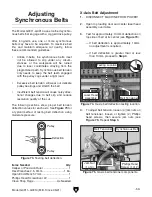
Figure 52. Example of output panel offset.
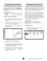
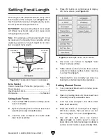
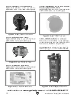
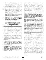
Primary Laser
Head Assembly
Secondary Laser
Head Assembly
Air Nozzle
Centerline
Distance
Figure 51. Example of measuring distance
between air nozzle centerlines.
-44-
Model G0911–G0914 (Mfd. Since 05/21)
Operating Dual Laser Head
(G0913/G0914)
The dual laser heads are NOT independent from
each other and operate in tandem. All opera-
tional settings are entered in RDWorks but can be
altered using the control panel.
1. DISCONNECT MACHINE FROM POWER!
2. Open top loading door and loosen (2) cap
screws securing left belt mounting bracket
on primary laser head assembly, position
primary laser head assembly as desired, then
secure cap screws (see
Figure 50).
3. Measure distance between primary and sec-
ondary laser head assembly air nozzle cen-
terlines (see
Figure 51).
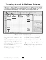
4. Open artwork file in RDWorks and select
"Output" tab of control panel, then select
"Enable offset of Laser2" (see
Figure 52).
5. Enter measured value from Step 3 in "X:"
box as a negative integer in millimeters
(e.g. "−50").
Note: Primary laser head can only be offset
towards negative X-axis.
6. Save artwork as .RD file (see Preparing
Artwork on Page 32) and transfer to machine
memory.
7. Perform Steps 1–19 of Operating Single
Laser Head beginning on Page 42.
Left Belt
Mounting Bracket
Primary Laser
Head Assembly
x 2
Summary of Contents for G0911
Page 100: ......


