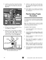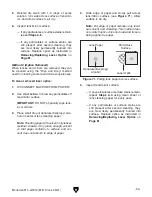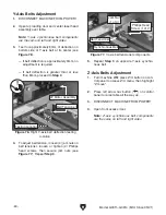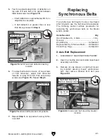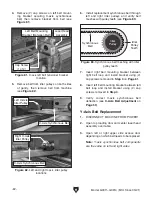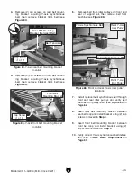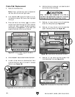
Figure 65. Z-Axis table lift components.
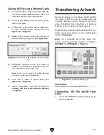
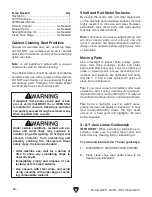
Figure 62. X-axis linear guideway and carriage.
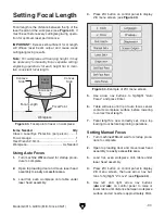
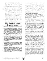
Figure 64. Right Y-axis linear guideway and
carriage.
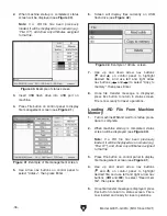
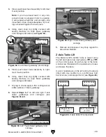
Figure 63. Left Y-axis linear guideway and
carriage.
Model G0911–G0914 (Mfd. Since 05/21)
-49-
3. Slowly push laser head assembly to left-most
X-axis position.
Note: If you move laser head, or any com-
ponent driven by stepper motor too quickly,
it will generate electricity and promptly stop
movement. Once charge dissipates, try mov-
ing component again at slower pace.
4. Using clean shop rag lightly covered with
sewing machine oil, wipe linear guideway
and carriage until clean (see
Figure 62).
5. Slowly push laser head assembly to right-
most X-axis position.
6. Using clean shop rag lightly covered with
sewing machine oil, wipe linear guideway
and carriage until clean.
7. Dip rag in oil and apply a thin coating across
entire surface of linear guideway.
8. Repeat Steps 3–7 on left and right Y-axis
linear guideways and carriages (see
Figures 63–64).
X-Axis Linear
Guideway
Carriage
Carriage
Left Y-Axis Linear Guideway
Right Y-Axis Linear Guideway
9. Remove and dispose of any shop rags left in
area when finished.
Z-Axis Table Lift
The Model G0911–G0914 table is raised using
the left and right arrow nav buttons (
and
)
on the control panel. At each corner of the table,
a leadscrew threaded with a leadscrew nut raises
and lowers the table.
A pair of leadscrews on the left and right side are
timed with one another by a synchronous belt,
belt tensioner, and stepper motor (see
Figure 65).
Leadscrew
(1 of 4)
Synchronous
Belt (1 of 2)
Stepper Motor
(1 of 2)
Belt Tensioner
(1 of 2)
Carriage
Summary of Contents for G0911
Page 100: ......

