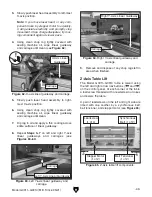

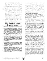


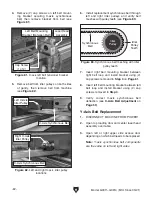

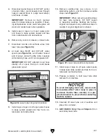


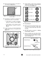
Figure 76. Right Y-axis belt deflection testing
location.
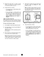
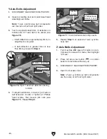
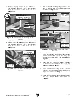
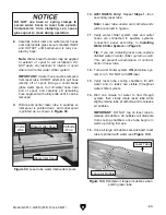
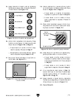
Figure 77. Y-axis belt tensioner components.
-60-
Model G0911–G0914 (Mfd. Since 05/21)
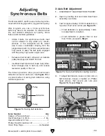
Y-Axis Belts Adjustment
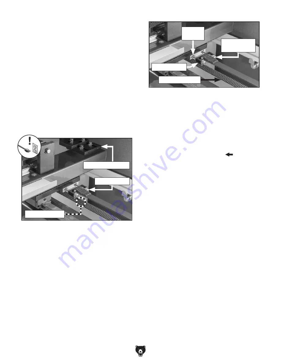
1. DISCONNECT MACHINE FROM POWER!
2. Open top loading door and center laser head
assembly over table.
Note: Y-axis synchronous belt components
are the same on left and right sides.
3. Test for approximately 8mm of deflection on
bottom side of Y-axis belt at its center (see
Figure 76).
— If belt deflection is approximately 8mm, no
adjustment is required.
— If belt deflection is greater than or less
than 8mm, proceed to
Step 4.
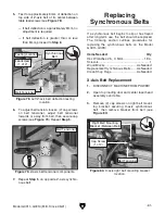
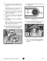
Z-Axis Belts Adjustment
1. Turn machine ON, press Z/U button on con-
trol panel to access Z/U menu, then highlight
"Z move".
2. Press left arrow nav button (
) on control
panel to raise table all the way up.
3. DISCONNECT MACHINE FROM POWER!
4. Open front access door.
Note: Z-axis synchronous belt components
are the same on left and right sides.
4. To adjust belt tension, loosen (4) jam nuts on
belt tensioner, loosen or tighten (2) Phillips
head screws, then secure jam nuts (see
Figure 77). Repeat Step 3.
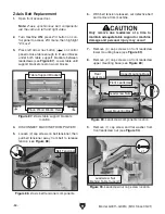
Testing Location
5. Repeat Step 3 on opposite Y-axis synchro-
nous belt.
Belt Tensioner
Jam Nut
(1 of 4)
Phillips Head
Screw (1 of 2)
Belt Tensioner
Synchronous Belt
#2 Mirror Assembly
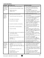
Summary of Contents for G0911
Page 100: ......


