
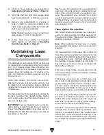


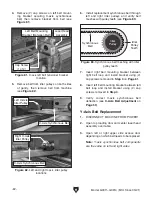

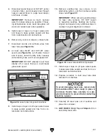


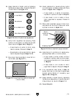

Figure 78. Left Z-axis belt deflection testing
location.
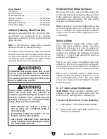
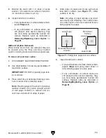
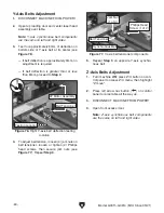
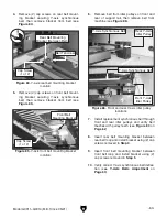
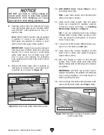
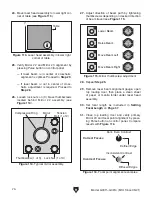
Figure 79. Z-axis belt tensioner components.
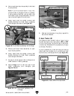
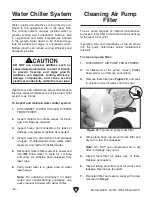
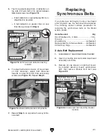
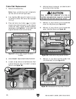
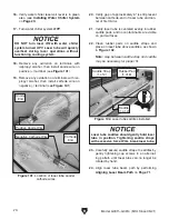
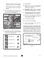
Figure 80. X-axis right belt mounting bracket
location.
Model G0911–G0914 (Mfd. Since 05/21)
-61-
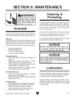
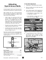
5. Test for approximately 8mm of deflection on
top side of Z-axis belt at its center between
table leadscrews (see
Figure 78).
— If belt deflection is approximately 8mm, no
adjustment is required.
— If belt deflection is greater than or less
than 8mm, proceed to
Step 6.
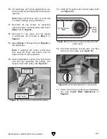
7. Repeat Step 5 on opposite Z-axis synchro-
nous belt.
If a synchronous belt begins to slip or has frayed
after long-term use, the belt should be replaced.
The following section outlines procedures for
replacing the synchronous belts on the Model
G0911–G0914.
Items Needed
Qty
Hex Wrenches 2.5, 3, 5mm .........................1 Ea.
Scissors ............................................................. 1
Wood Blocks ..................................... As Needed
Replacement Synchronous Belts ...... As Needed
Clean Shop Rags .............................. As Needed
X-Axis Belt Replacement
1. DISCONNECT MACHINE FROM POWER!
2. Open top loading door and center laser head
assembly over table.
3. Remove (2) cap screws on right belt mount-
ing bracket securing X-axis synchronous
belt, then remove bracket from belt (see
Figure 80).
Replacing
Synchronous Belts
Right Belt Mounting
Bracket (Between Belt)
6. To adjust belt tension, loosen (2) cap screws
on belt tensioner, adjust belt tensioner
towards or away from belt, then secure cap
screws (see
Figure 79). Repeat Step 5.
Testing Location
Belt Tensioner
Synchronous
Belt
Leadscrew
(1 of 2)
Cap Screw
(1 of 2)
Belt Tensioner
Belt Tensioner
x 2
Summary of Contents for G0911
Page 100: ......