Only remove one leadscrew at a time to
maintain adequate table support or machine
damage and personal injury may occur!
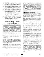
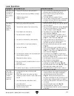
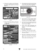
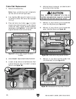
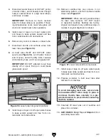
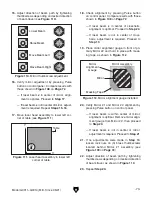
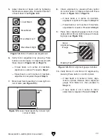
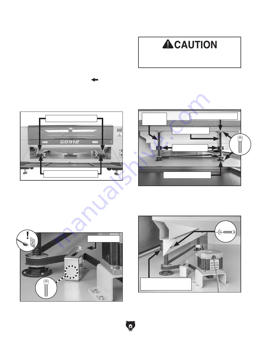
Figure 87. Z-axis table support brackets
location.
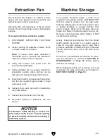
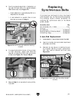
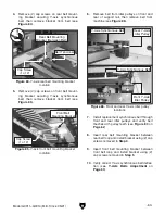
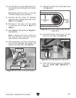
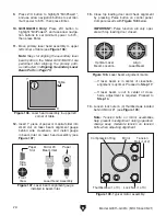
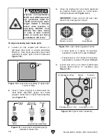
Figure 90. Leadscrew nut cap screw location.
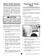
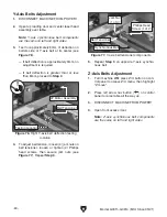
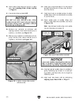
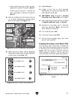
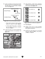
Figure 89. Leadscrew components location.
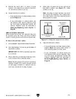
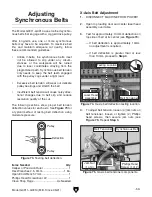
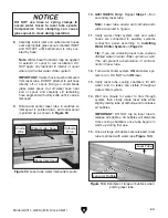
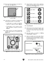
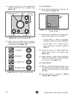
Figure 88. Z-axis belt tensioner components.
x 1
x 6
-64-
Model G0911–G0914 (Mfd. Since 05/21)
Z-Axis Belt Replacement
1. Open front access door.
Note: Z-axis synchronous belt components
are the same on left and right sides.
2. Turn machine ON, press Z/U button on con-
trol panel to access Z/U menu, then highlight
"Z move".
3. Press left arrow nav button (
) on control
panel to raise table enough to fit wood blocks
under both table support brackets between
leadscrews (see
Figure 87). Lower table until
support brackets rest on wood blocks.
4. DISCONNECT MACHINE FROM POWER!
5. Loosen (2) cap screws on belt tensioner, then
pull belt tensioner away from belt to release
tension (see
Figure 88).
6. With belt tension released, cut defective belt
and remove from machine.
7. Remove (4) cap screws on front leadscrew
lower mounting base (see
Figure 89).
8. Remove (2) cap screws on front leadscrew
upper mounting base (see
Figure 89).
9. Remove (1) cap screw and flat washer from
front leadscrew nut (see
Figure 90).
Rear
Leadscrew
Upper Mounting Base
Lower Mounting Base
Leadscrew Nuts
Front Leadscrew
Leadscrew Nut
(Behind Table Support)
Table Support Brackets
Place Wood Blocks Here
x 2
Belt Tensioner
Summary of Contents for G0911
Page 100: ......


