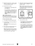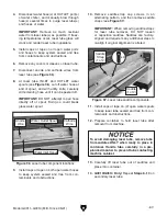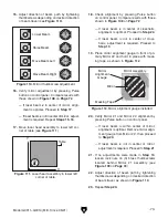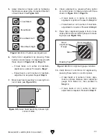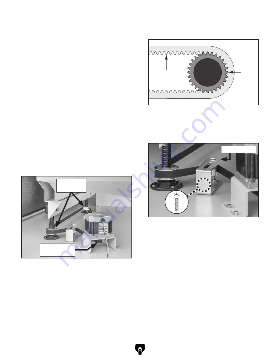
Synchronous
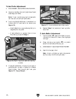
Belt
Idler
Pulley
Teeth
Idler
Pulley
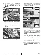
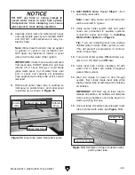
Figure 92. Synchronous belt meshing with idler
pulley teeth.
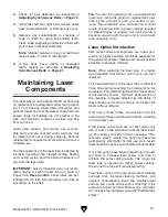
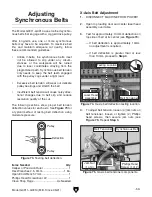
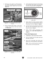
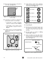
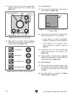
Figure 91. Synchronous belt around pulleys.
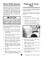
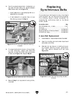
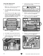
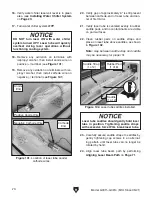
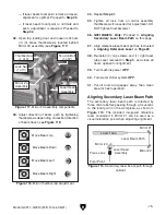
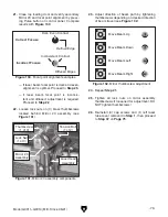
Figure 93. Z-axis belt tensioner components.
Model G0911–G0914 (Mfd. Since 05/21)
-65-
10. Lift leadscrew and place replacement syn-
chronous belt around leadscrew lower mount-
ing base.
Note: Keep synchronous belt out of the way
to prevent damage during installation.
11. Re-install (6) cap screws on leadscrew
upper and lower mounting bases removed in
Steps 7–8 on Page 64.
12. Re-install (1) cap screw and flat washer
on leadscrew nut removed in
Step 9 on
Page 64.
13. Repeat Steps 7–12 beginning on Page 64 on
rear leadscrew.
Note: If replacing left Z-axis synchronous
belt, open left lower side access door for
easier access to rear leadscrew.
14. Install replacement synchronous belt around
front and rear leadscrew idler pulleys, and
stepper motor idler pulley (see
Figure 91).
15. Verify belt meshes with all idler pulley teeth
(see
Figure 92).
16. Push belt tensioner towards belt, and then
secure (2) cap screws (see
Figure 93).
17. Verify correct Z-axis synchronous belt deflec-
tion (see
Z-Axis Belts Adjustment on
Page 60).
Stepper Motor
Idler Pulley
Leadscrew
Idler Pulleys
x 2
Belt Tensioner
Summary of Contents for G0911
Page 100: ......

