


To reduce your risk of
serious injury, read this
entire manual BEFORE
using machine.
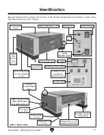
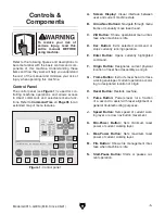
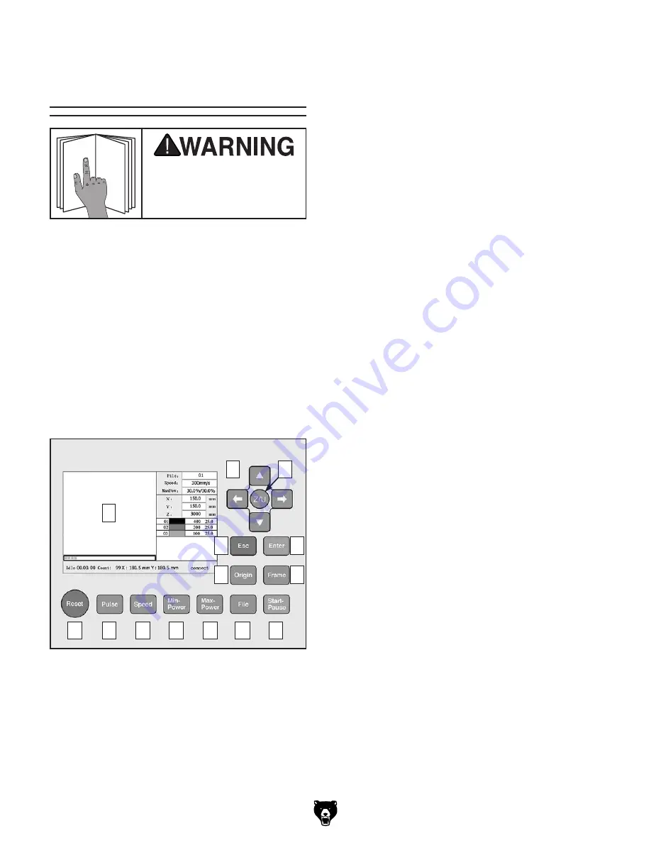
Figure 1. Control panel.
Model G0911–G0914 (Mfd. Since 05/21)
-5-
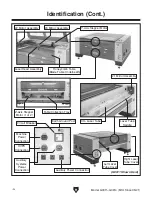
Refer to the following figures and descriptions to
become familiar with the basic controls and com-
ponents of this machine. Understanding these
items and how they work will help you understand
the rest of the manual and minimize your risk of
injury when operating this machine.
Controls &
Components
A. Screen Display: Visual interface between
user and current machine state.
B. Arrow Nav Buttons: Navigate through menu
items or manually move laser head.
C. Z/U Button: Shows operational menu inter-
face when machine is idle.
D. Esc Button: Exits selected command or
stops currently running operation.
E. Enter Button: Opens currently highlighted
command.
F. Origin Button: Designates current physical
location of laser head assembly as origin.
G. Frame Button: Instructs laser head to trace
working envelope of current operation accord-
ing to designated location of origin.
H. Reset Button: Restarts machine.
I. Pulse Button: Powers laser for a fraction
of a second to assist with laser alignment or
general troubleshooting purposes.
J. Speed Button: Sets speed of current work-
ing layer or arrow nav button movement.
K. Min-Power Button: Sets minimum laser
power of current working layer.
L. Max-Power Button: Sets maximum laser
power of current working layer.
M. File Button: Shows file management inter-
face when machine is idle.
N. Start-Pause Button: Starts or pauses cur-
rent operation.
The control panel (see
Figure 1) is used for con-
trolling machine operations and allows access
to direct commands and selectable menu func-
tions. Refer to
Command Tree on Page 95 for an
extended map of menu features.
Control Panel
A
B
C
D
E
F
G
J
H
K
I
N
M
L
Summary of Contents for G0911
Page 100: ......


