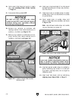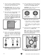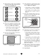
To avoid damaging laser tube, remove tube
from container ONLY when ready to place
in machine. Handle tube carefully in a pre-
planned manner to prevent tube contacting
machine cabinet.
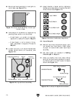
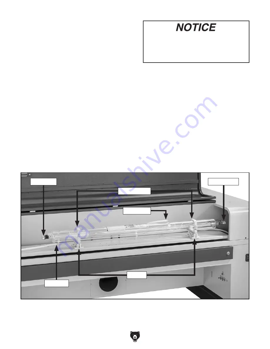
Figure 98. Laser tube compartment identification.
-68-
Model G0911–G0914 (Mfd. Since 05/21)
Installing Laser Tube
1. Inspect laser tube saddles and rubber pads
for any debris or foreign material, and clean
as required (see
Figure 98).
IMPORTANT: When inspecting and setting
up machine for laser tube installation, DO
NOT loosen or reposition laser tube sad-
dles. Saddles are factory-aligned and require
many additional steps to re-align if original
alignment is altered.
2. Carefully open laser tube shipping container.
Note: DO NOT destroy or discard laser tube
shipping container. Retain original box for
ordering replacement tubes, or in the event
of damage caused during shipping.
3. Remove dust caps or tape (if installed) from
laser tube.
IMPORTANT:
DO NOT force caps off water
spout if they cannot be removed by hand.
Carefully cut them off using utility knife.
4. Carefully remove laser tube from shipping
container, and position anode-end on anode
side of tube compartment (see
Figure 98).
5. Gently place laser tube in saddles.
6. Position cathode-end of laser tube so there is
a gap of approximately 6" between end and
center of first mirror (see
Figure 98).
Note: Laser tube has labels showing sug-
gested support location for saddles.
7. Verify inlet and outlet hoses will not interfere
with closed doors or covers, and hoses are
free of kinks that could potentially restrict
water flow to laser tube.
Outlet Hose
Anode End
Cathode End
Saddles
Saddle Straps
Inlet Hose
Summary of Contents for G0911
Page 100: ......

