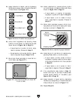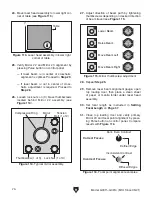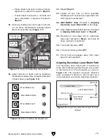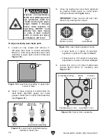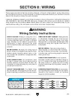
Operator and bystanders
MUST wear ANSI-approved
eye protection rated for
10,600 nm (10.6 µm) wave-
length CLASS 4 infrared
lasers when machine is
operating. NEVER look
directly into laser beam
or stare at laser contact
point, or severe eye injury
or blindness will occur!
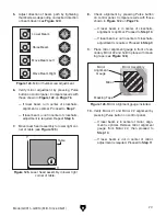
Laser Head Assembly
Front
View
Side
View
Paper
Slot
Mirror #3
Beam Inlet
Paper
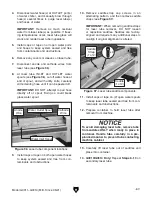
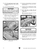
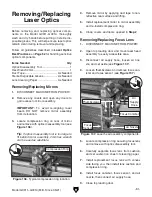
Figure 121. Laser beam alignment gauge
installed in beam inlet.
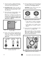
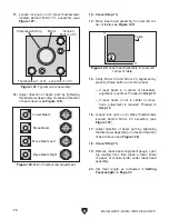
Optimal Laser
Beam Location
Align
Laser Beam
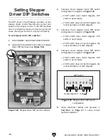
Figure 122. Laser beam alignment marks.
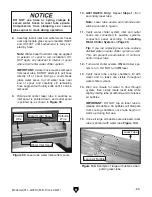
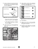
Mirror
Tension
Bolt (1 of 2)
Compression Ring
Thumbscrew (1 of 3)
Lock Nut (1 of 3)
Figure 123. Typical mirror assembly.
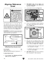
X
Y
Table
Figure 120. Laser head assembly in upper right
corner of table.
-76-
Model G0911–G0914 (Mfd. Since 05/21)
3.
Close top loading door and check alignment
by pressing Pulse button on control panel.
Compare results with
Figure below.
IMPORTANT: Pulse function will only oper-
ate with top loading door closed.
— If laser beam is in center of crosshairs,
alignment is optimal. Proceed to
Step 7.
— If laser beam is not in center of crosshairs,
adjustment is required. Proceed to
Step 4.
4.
L
oosen lock nuts on (3) brass thumbscrews
located behind Mirror #1 assembly (see
Figure 123).
2.
Insert 1" piece of paper or manila folder into
laser beam alignment gauge, and install
gauge in beam inlet on laser head assembly
(see
Figure 121).
To align secondary laser beam path:
1. Loosen (4) cap screws and remove (1)
left laser tube cover to access secondary
Mirror #1, then m
ove secondary laser head
assembly to upper right corner of table (see
Figure 120).
Summary of Contents for G0911
Page 100: ......

