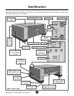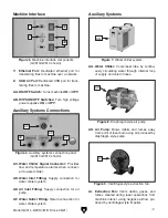
Figure 4. Power connections (G0913/G0914
shown).
Figure 3. Laser tube (removed from machine for
clarity).
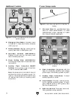
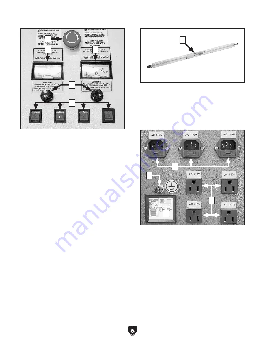
Figure 2. Location of additional controls (G0913/
G0914 shown).
-6-
Model G0911–G0914 (Mfd. Since 05/21)
O. Emergency Stop Button: Disables power
to machine. To reset, twist button clockwise
until it pops out.
P. Primary Ammeter: Displays current used by
primary laser tube in milliamperes (mA).
Q. Secondary Ammeter (G0913/G0914):
Displays current used by secondary laser
tube in milliamperes (mA).
R. Power Setting Dials (G0913/G0914):
Provide power adjustment of laser tubes dur-
ing operation.
S. Auxiliary Power Connection ON/OFF
Switches: Turn auxiliary power connections
on rear of machine
ON or OFF.
Note: The Model G0911 and G0912 have (3)
switches that control (3) auxiliary power con-
nections. The Model G0913 and G0914 have
(4) switches that control (4) auxiliary power
connections.
Additional Controls
Power Components
T. CO
2
Laser Tube:
CO
2
gas-filled laser tube
rated for 100W (G0911/G0913) or 130W
(G0912/G0914) output. Operates at 10,600
nm (10.6 µm) infrared wavelength.
T
U. Power Connections:
Receptacles with 10A
fuses for connecting machine, high voltage
power supply, and auxiliary systems to power.
V. Auxiliary Power Connections:
Connect
auxiliary systems to power.
W. Circuit Breaker:
Provides overload protec-
tion for machine electrical system. To reset,
place ON/OFF switch in OFF position, then
flip circuit breaker switch.
X. Earth Ground Post: Dissipates static elec-
tricity generated during operation.
O
P
Q
R
S
W
U
X
V
Summary of Contents for G0911
Page 100: ......


