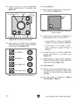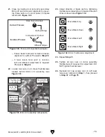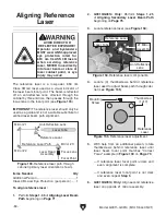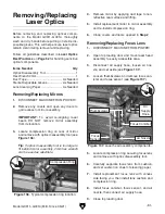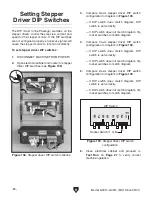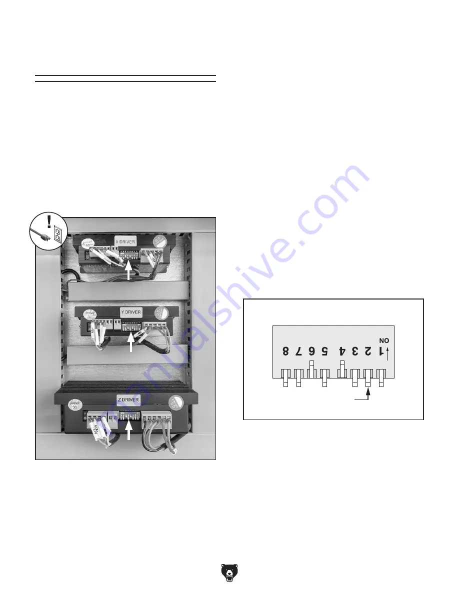
Figure 138. Stepper driver DIP switch locations.
DIP Switch
Rocker Switch (1 of 8)
Figure 139. Stepper driver DIP switch
configuration.
-82-
Model G0911–G0914 (Mfd. Since 05/21)
The DIP (Dual In-line Package) switches on the
stepper drivers control the step size, current, and
speed of the stepper motors. If the DIP switches
are not configured properly, erroneous signals will
cause the stepper motors to function incorrectly.
To set stepper driver DIP switches:
1. DISCONNECT MACHINE FROM POWER!
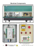
2. Open electrical cabinet and locate (3) stepper
driver DIP switches (see
Figure 138).
Setting Stepper
Driver DIP Switches
3. Compare X-axis stepper driver DIP switch
configuration to diagram in
Figure 139.
— If DIP switch does match diagram, DIP
switch is set correctly.
— If DIP switch does not match diagram, flip
rocker switches to match diagram.
4. Compare Y-axis stepper driver DIP switch
configuration to diagram in
Figure 139.
— If DIP switch does match diagram, DIP
switch is set correctly.
— If DIP switch does not match diagram, flip
rocker switches to match diagram.
5. Compare Z-axis stepper driver DIP switch
configuration to diagram in
Figure 139.
— If DIP switch does match diagram, DIP
switch is set correctly.
— If DIP switch does not match diagram, flip
rocker switches to match diagram.
6. Close electrical cabinet and proceed to
Test Run on Page 27 to verify correct
machine operation.
Summary of Contents for G0911
Page 100: ......


