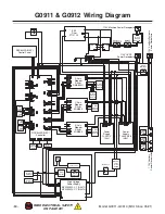
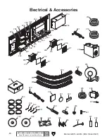
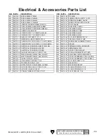

134
135
(G0913)
(G0914)
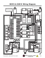
126
(G0913)
(G0914)
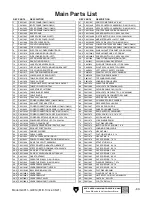
134-1
134-2
134-14
134-3
134-21
134-22
134-24
134-23
134-4
134-5
134-6
134-7
134-18
134-19
134-8
134-9
134-17
134-10
134-11
134-12
134-15
134-16
134-17
134-13
134-20
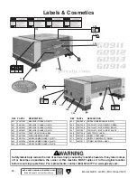
101-1
101
159
160
167
168
101-2
101-3
101-4
101-5
101-6
101-7
101-8
101-9
101-10
102
103
133
104
106
131
(G0913)
(G0914)
106-1
106-2
106-3
106-4
106-5
106-6
106-7
106-8
106-9
106-10
106-11
106-12
106-13
106-14
106-15
106-16
106-16
106-17
106-18
106-19
106-20
106-21
106-22
106-23
106-24
106-25
110
111
112
113
114
161
163
164
162
115
116
118
117
119
120
120
121
147
148
149
150
146
122
123
136
124
125
128
129
151
152
130
132
132
153
153
154
155
156
156
156
159
159
160
160
156
155
133
133
107
142
142
142
141
165
140
140
143
141
141
140
157
157
157
158
147
108
159
116 137
157
120
120
129
154
155
155
151
130
130
130
130
130
138
138
144
144
144
145
165
166
139
-90-
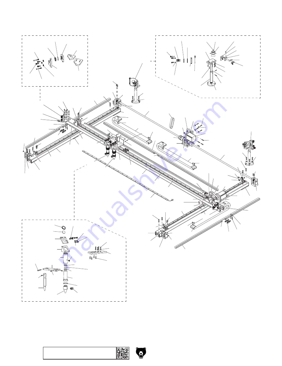
Model G0911–G0914 (Mfd. Since 05/21)
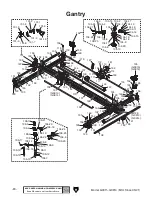
BUY PARTS ONLINE AT GRIZZLY.COM!
Scan QR code to visit our Parts Store.
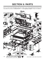
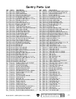
Gantry
Summary of Contents for G0911
Page 100: ......


